75
Water Circuit Installation
Due to our policy of continuous product innovation, some specifications may change without notification.
©LG Electronics U.S.A., Inc., Englewood Cliffs, NJ. All rights reserved. “LG” is a registered trademark of LG Corp.
WATER CIRCUIT INSTALLATION
Design Steps
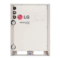
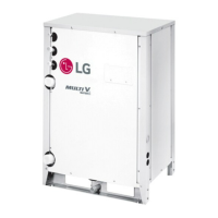
The Multi V Water IV Water Source Unit requires a water cooling / heating source. This year-round heating and cooling system has a two
(2) pipe closed loop, continuously-circulating water circuit. This water circuit helps maintain water temperature at 23°F to 113°F for cooling
mode and 23°F to 113°F for heating mode. Refer to the capacity tables in the Multi V Water IV Water Source Unit Engineering Manual for
performance at different entering water temperatures. At the high end of this temperature range, heat is rejected through a cooling tower (dry
cooler or geothermal well), while at the low end of the temperature range an auxiliary heat source like a boiler, solar panel, or geothermal
well adds heat.
Piping, pumps, and accessories must be sized to provide adequate water flow to the water source unit based on nominal flow rates listed for
each model number.
Design Schematic
Multi V Water IV Water Source Units have factory installed stainless steel plate heat exchangers. To protect these heat exchangers, using
closed cooling towers is recommended. If open cooling towers or other open loop systems are used, add an intermediate heat exchanger
to protect the water source unit from contaminants and debris that may foul or clog the heat exchanger. Open loop systems without an
intermediate heat exchanger are not recommended due to risk of freezing, reduction of flow due to scaling or clogging, or other potential
problems caused by improper water quality.
Figure 58: Cooling Cycle Diagram.
Water Circuit Design
Figure 59: Heating Cycle Diagram.

 Loading...


