Due to our policy of continuous product innovation, some specifications may change without notification.
©LG Electronics U.S.A., Inc., Englewood Cliffs, NJ. All rights reserved. “LG” is a registered trademark of LG Corp.
125
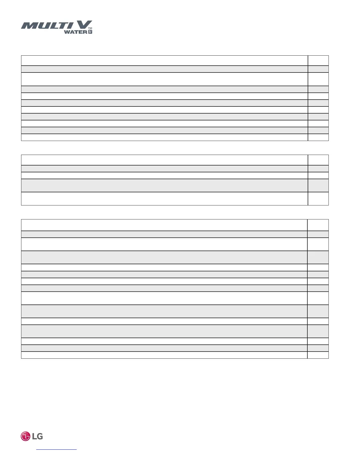
INSTALLATION CHECKLIST
PAGE 2
Water Piping
Description Check
A No. 50 mesh (or better) minimum one inch diameter strainer is installed on the inlet pipe.
Strainer service isolation valves, (optional bypass line and shutoff valve) provided on both ends of strainer. Strainer drain line
installed.
A balancing valve has been installed.
A flow switch has been installed.
Thermometers (or Pete’s plugs) are installed on the inlet and outlet pipes.
(Optional) Pressure gauges were installed on the inlet and outlet pipes.
Piping is insulated properly per the design engineer’s specifications.
Pipes are properly supported. No lateral pressure is present on the inlet and outlet connections.
The inlet and outlet pipes are connected at the water source unit. Water flow direction is correct (pipes are not reversed).
Shutoff valves present at inlet and outlet of the water source unit.
Condensate Pump / Drain Installation
Description Check
Indoor unit condensate drain pipes were installed correctly.
All condensate vertical risers are equal to or less than 27-1/2″ from the bottom of the indoor unit.
Indoor units with condensate pumps were leveled. Units with gravity drains were leveled or slightly canted toward the drain
connection and are properly supported.
Pumped condensate drain lines were properly connected (do not have traps, and connect to the top surface of the main drain
line).
Power Wire and Communications Cables
Description Check
Appropriate crimping tool used to attach ring or spade terminals at all power wiring and control cable terminations.
Verify all ring and spade terminals are copper bearing in all communications daisy chains. Galvanized or nickel plated steel
connectors were not used.
Correct input voltage (208-230V or 460V as specified on water source unit nameplate) was connected to proper power input
terminals of water source unit
Ground wire was installed and properly terminated at the water source unit.
The power supplied was clean with voltage fluctuations within specifications (±10% of nameplate).
Power wiring to the water-source unit(s) was installed per all local electrical code requirements.
Power wiring to each indoor unit was installed per all local electrical code requirements.
Communications cable between the water source unit and indoor units was connected in a daisy chain configuration (i.e., single
parallel chain). No “Star” or multiple parallel circuits. No cable splices or wire caps were used to connect communications cables.
LG-supplied cable was used between each indoor unit and its zone controller. No cables were spliced and no wire caps are
present.
Communication type RS-485–BUS type. Communication cables are connected in a daisy chain configuration from unit to unit.
All communications cables are a minimum of 18-Gauge, two conductor, stranded and shielded with insulation material per local
code. Cable segment shields were tied together. Cable shield is grounded at the water source unit only.
All power and control wires were properly separated using the recommended distance provided in the product installation manual.
Only LG-supplied Y-cables and extension cables were used between indoor units.
Flow switch communications cable has been properly terminated at the switch and the water source unit.

 Loading...

