14
MULTI V Water IV System Installation Manual
Due to our policy of continuous product innovation, some specifications may change without notification.
©LG Electronics U.S.A., Inc., Englewood Cliffs, NJ. All rights reserved. “LG” is a registered trademark of LG Corp.
1
Nominal capacity is outside of AHRI Standard 1230 and based on the following conditions:
• Cooling – Indoor 80°F DB / 66°F WB
Water Temperature Entering: 86°F
• Heating – Indoor 68°F DB
Water Temperature Entering: 68°F
2
When entering water temperature is lower than 59ºF, variable water flow control kit PWFCKN000
is required.
3
Sound pressure levels are tested in an anechoic chamber under ISO 3745 standard.
4
Value is calculated as follows: Δt = Total Heat of Rejection/(Nominal Flow Rate x 500).
5
Refer to the Refrigerant Piping section of this manual for correct line sizing. Contractor must use LG
manufactured Y-Branch and Header Kits only. Designer must verify refrigerant piping design configura-
tion using LG’s computerized refrigerant piping software (LATS Multi V) to validate the pipe design.
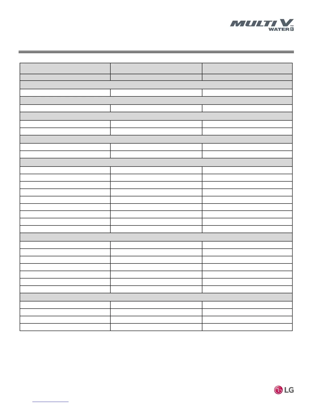
Table 6: Triple-Frame 460V Heat Pump Units
GENERAL DATA
ARWN Series Heat Pump Water Source Unit Specications
Combination Unit Model Number
40.0 Ton
ARWN480DAS4
48.0 Ton
ARWN576DAS4
Individual Component Model Numbers
ARWN144DAS4 x 2 +
ARWN192DAS4 x 1 ARWN192DAS4 x 3
Cooling Performance
Nominal Cooling Capacity (Btu/h)
1
480,000 576,000
Heating Performance
Nominal Heating Capacity (Btu/h)
1
540,000 648,000
Operating Range (Entering Water Temperature)
Cooling (°F)
2
23 – 113 23 – 113
Heating (°F)
14 – 113 14 – 113
Compressor
Inverter Quantity
HSS DC Scroll x 3 HSS DC Scroll x 3
Oil/Type
PVE/FVC68D PVE/FVC68D
Unit Data
Refrigerant Type
R410A R410A
R410A Refrigerant Factory Charge (lbs)
6.6 + 6.6 + 6.6 6.6 + 6.6 + 6.6
Refrigerant Control/Location
EEV/Indoor Unit EEV/Indoor Unit
Max. Number Indoor Units/System
64 64
Sound Pressure dB(A)
3
Cooling/Heating
60/62 60/62
Net Unit Weight (lbs.)
309 x 3 309 x 3
Shipping Weight (lbs.)
331 x 3 331 x 3
Communication Cables
2 x 18 AWG 2 x 18 AWG
Heat Rejected to Equipment Room (Btu/h)
7,275 7863
Heat Exchanger (Stainless Steel Plate)
Maximum Pressure Resistance (psi)
640 640
Flow at Rated Condition (GPM)
35.5 + 35.5 + 50.7 50.7 + 50.7 + 50.7
Range of Flow (GPM)
48.7 – 182.6 60.8 – 228.2
Total Heat of Rejection (Btu/h)
190,100 + 190,100 + 253,500 253,500 + 253,500 + 253,500
Total Heat of Absorption (Btu/h)
146,800 + 146,800 + 193,600 193,600 + 193,600 + 193,600
Pressure Drop (ft-wg)
4.7 + 4.7 + 9.2 9.2 + 9.2 + 9.2
Δt
4
(°F)
10.4 10.0
Piping
5
Liquid Line Connection (in., OD)
1/2 + 1/2 + 1/2 Braze 1/2 + 1/2 + 1/2 Braze
Vapor Line Connection (in., OD)
1-1/8 + 1-1/8 + 1-1/8 Braze 1-1/8 + 1-1/8 + 1-1/8 Braze
Water Inlet/Outlet Connection Size (in)
(1-1/2 + 1-1/2 Fem) x3 (1-1/2 + 1-1/2 Fem) x3
Condensate Drain (in)
3/4 Female 3/4 Female

 Loading...

