16
MULTI V Water IV System Installation Manual
Due to our policy of continuous product innovation, some specifications may change without notification.
©LG Electronics U.S.A., Inc., Englewood Cliffs, NJ. All rights reserved. “LG” is a registered trademark of LG Corp.
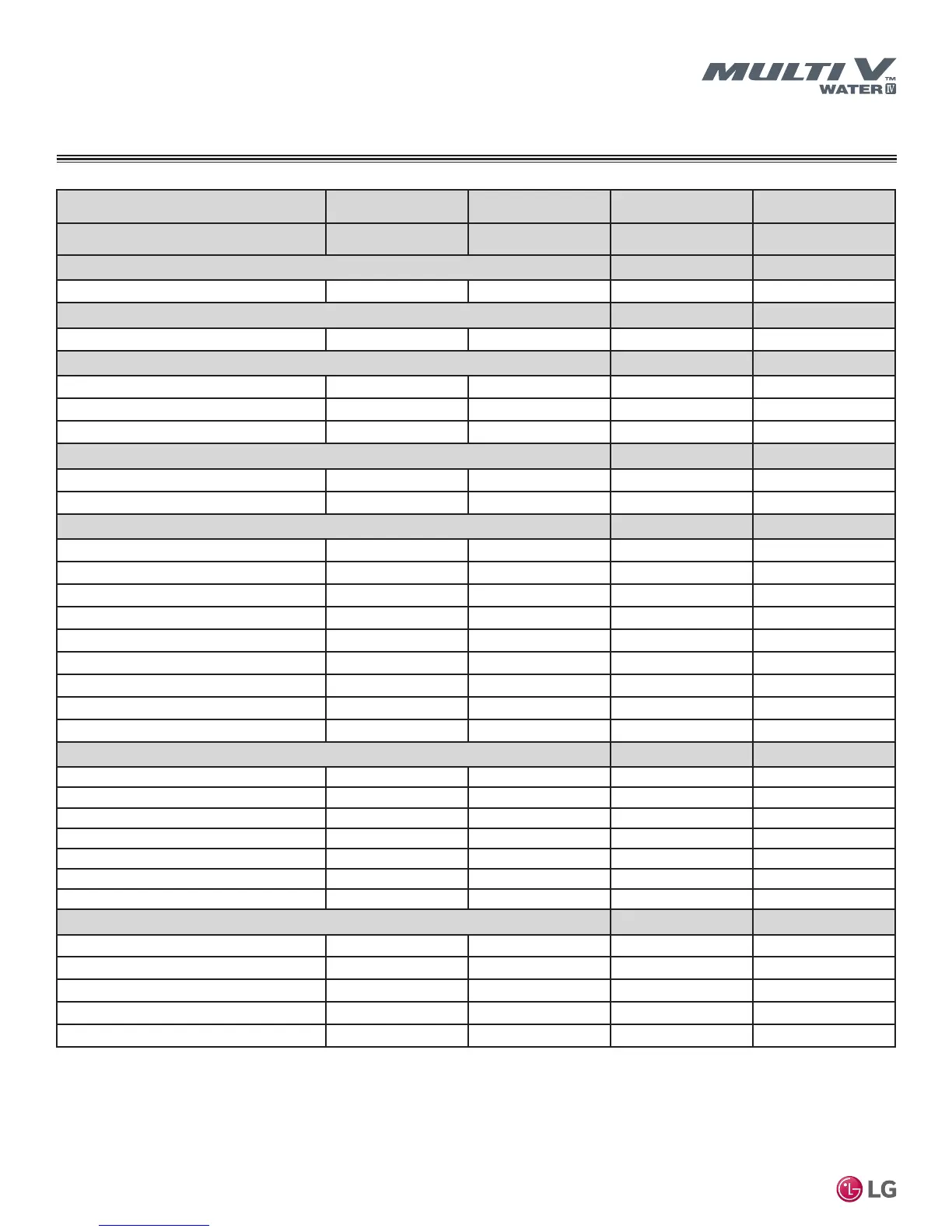
Table 8: Dual-Frame 208-230V Heat Recovery Units.
GENERAL DATA
ARWB Series Heat Recovery Water Source Unit Specications
Combination Unit Model Number
14.0 Ton
ARWB168BAS4
16.0 Ton
ARWB192BAS4
18.0 Ton
ARWB216BAS4
24.0 Ton
ARWB288BAS4
Individual Component Model Numbers
ARWB072BAS4 x 1
+ ARWB096BAS4 x 1
ARWB072BAS4 x 1
+ ARWB121BAS4 x 1
ARWB072BAS4 x 1
+ ARWB144BAS4 x 1
ARWB144BAS4 x 2
Cooling Performance
Nominal Cooling Capacity (Btu/h)
1
168,000 192,000 216,000 288,000
Heating Performance
Nominal Heating Capacity (Btu/h)
1
189,000 216,000 243,000 324,000
Operating Range (Entering Water Temperature)
Cooling (°F)
2
23 – 113 23 – 113 23 – 113 23 – 113
Heating (°F)
14 – 113 14 – 113 14 – 113 14 – 113
Synchronous Operation (°F)
23 – 113 23 – 113 23 – 113 23 – 113
Compressor
Inverter Quantity
HSS DC Scroll x 2 HSS DC Scroll x 2 HSS DC Scroll x 2 HSS DC Scroll x 2
Oil/Type
PVE/FVC68D PVE/FVC68D PVE/FVC68D PVE/FVC68D
Unit Data
Refrigerant Type
R410A R410A R410A R410A
R410A Refrigerant Factory Charge (lbs)
12.8 + 12.8 12.8 + 12.8 12.8 + 12.8 12.8 + 12.8
Refrigerant Control/Location
EEV/Indoor Unit EEV/Indoor Unit EEV/Indoor Unit EEV/Indoor Unit
Max. Number Indoor Units/System
29 32 35 45
Sound Press dB(A)
3
Cooling/Heating
55/56 54/60 57/57 59/58
Net Unit Weight (lbs.)
280 + 280 280 + 280 280 + 280 280 + 280
Shipping Weight (lbs.)
302 + 302 302 + 302 302 + 302 302 + 302
Communication Cables
2 x 18 AWG 2 x 18 AWG 2 x 18 AWG 2 x 18 AWG
Heat Rejected to Equipment Room (Btu/h)
4,304 4,645 4,816 5,328
Heat Exchanger (Stainless Steel Plate)
Maximum Pressure Resistance (psi)
640 640 640 640
Flow at Rated Condition (GPM)
25.4 + 20.3 30.4 + 20.3 35.5 + 20.3 35.5 + 35.5
Range of Flow (GPM)
18.3 – 68.6 20.3 – 76.1 22.3 – 83.7 28.4 – 106.5
Total Heat of Rejection (Btu/h)
94,400 + 126,700 94,400 + 157,400 94,400 + 190.100 190,100 + 190,100
Total Heat of Absorption (Btu/h)
73,200 + 96,800 73,200 + 122,000 73,200 + 145,200 145,200 + 145,200
Pressure Drop (ft-wg)
3.7 + 4.7 3.7 + 6.9 3.7 + 9.2 9.2 + 9.2
Δt
4
(°F)
9.6 9.9 10.2 10.7
Piping
5
Liquid Line Connection (in., OD)
3/8 + 3/8 Braze 1/2 + 3/8 Braze 1/2 + 3/8 Braze 1/2 + 1/2 Braze
Low Press Vapor Line Conn (in., OD)
7/8 + 7/8 Braze 7/8 + 1-1/8 Braze 7/8 + 1-1/8 Braze 1-1/8 + 1-1/8 Braze
High Press Vapor Line Conn (in., OD)
3/4 + 3/4 Braze 3/4 + 3/4 Braze 3/4 + 3/4 Braze 3/4 + 3/4 Braze
Water Inlet/Outlet Connection (in)
(1-1/2 + 1-1/2 Fem) x2 (1-1/2 + 1-1/2 Fem) x2 (1-1/2 + 1-1/2 Fem) x2 (1-1/2 + 1-1/2 Fem) x2
Condensate Drain (in)
3/4 Female 3/4 Female 3/4 Female 3/4 Female
1
Nominal capacity is outside of AHRI Standard 1230 and based on the following conditions:
• Cooling – Indoor 80°F DB / 66°F WB
Water Temperature Entering: 86°F
• Heating – Indoor 68°F DB
Water Temperature Entering: 68°F
2
When entering water temperature is lower than 59ºF, variable water flow control kit PWFCKN000
is required.
3
Sound pressure levels are tested in an anechoic chamber under ISO 3745 standard.
4
Value is calculated as follows: Δt = Total Heat of Rejection/(Nominal Flow Rate x 500).
5
Refer to the Refrigerant Piping section of this manual for correct line sizing. Contractor must use LG
manufactured Y-Branch and Header Kits only. Designer must verify refrigerant piping design configura-
tion using LG’s computerized refrigerant piping software (LATS Multi V) to validate the pipe design.

 Loading...

