66
MULTI V Water IV System Installation Manual
Due to our policy of continuous product innovation, some specifications may change without notification.
©LG Electronics U.S.A., Inc., Englewood Cliffs, NJ. All rights reserved. “LG” is a registered trademark of LG Corp.
Pipe Layout
REFRIGERANT PIPING INSTALLATION
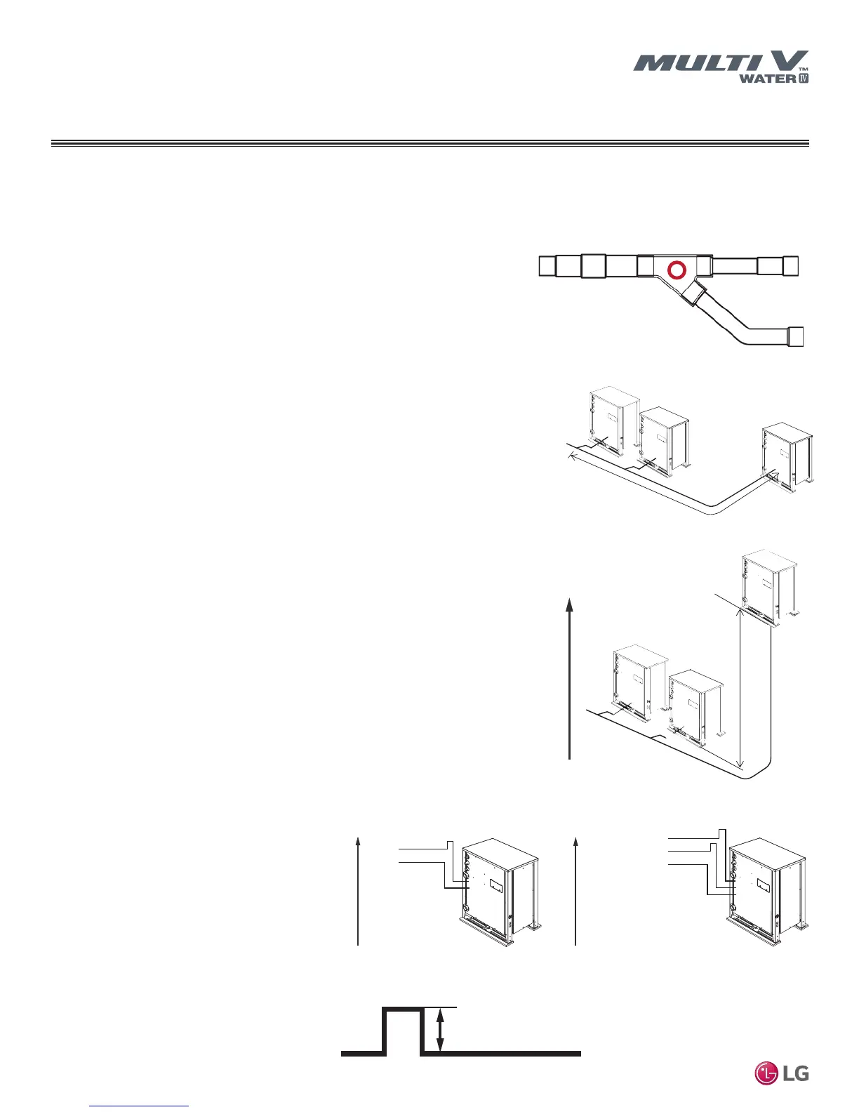
Figure 38: Elevation Difference Between Water
Source Units.
Refrigerant Piping for Separated Water Source Units
Dual-frame and triple-frame systems should be installed with all water source units located next to each other. In conditions where the dual-
frame or triple-frame water source units need to be separated, the following rules must be followed:
1. Measurements.
All measurements should be made from the union center of the water source unit
Y-branch.
2. Maximum pipe length from first water source unit Y-branch to farthest water source
unit.
Total pipe length from the first outdoor unit Y-branch to the piping connection at the
farthest outdoor unit must not exceed thirty-three (33) feet.
33 Feet
(Max.)
3. Elevation difference between water source units.
The elevation difference between the highest and lowest elevation water source unit
must not exceed sixteen (16) feet.
Suction
Liquid
To IDUs
Elevation
Heat Pump
Low Pressure Vapor
Liquid
To IDUs
Elevation
Heat Recovery
High Pressure Vapor
≥8 inches
Trapping
1. When required, all traps must be inverted type
traps ≥8″ in the vapor line(s).
a. Heat pump water source units would be
trapped in the suction vapor line, and heat
recovery water source units would be trapped
in the high AND low pressure vapor lines.
b. Inverted traps are defined as any piping that
is ≥8″ in a vertical direction up the horizontal
pipe it elevates from.
Figure 39: Y-branch Measurement Location.
Figure 40: Maximum PIpe Length from First WSU
Y-branch to Farthest WSU.
Figure 41: Traps for Heat Pump and Heat Recovery Units.
Figure 42: Close Up of An Inverted Oil Trap.
To IDUs/
HRUs
16 Feet
(Max)

 Loading...

