81
Water Circuit Installation
Due to our policy of continuous product innovation, some specifications may change without notification.
©LG Electronics U.S.A., Inc., Englewood Cliffs, NJ. All rights reserved. “LG” is a registered trademark of LG Corp.
WATER CIRCUIT INSTALLATION
Piping System Specications
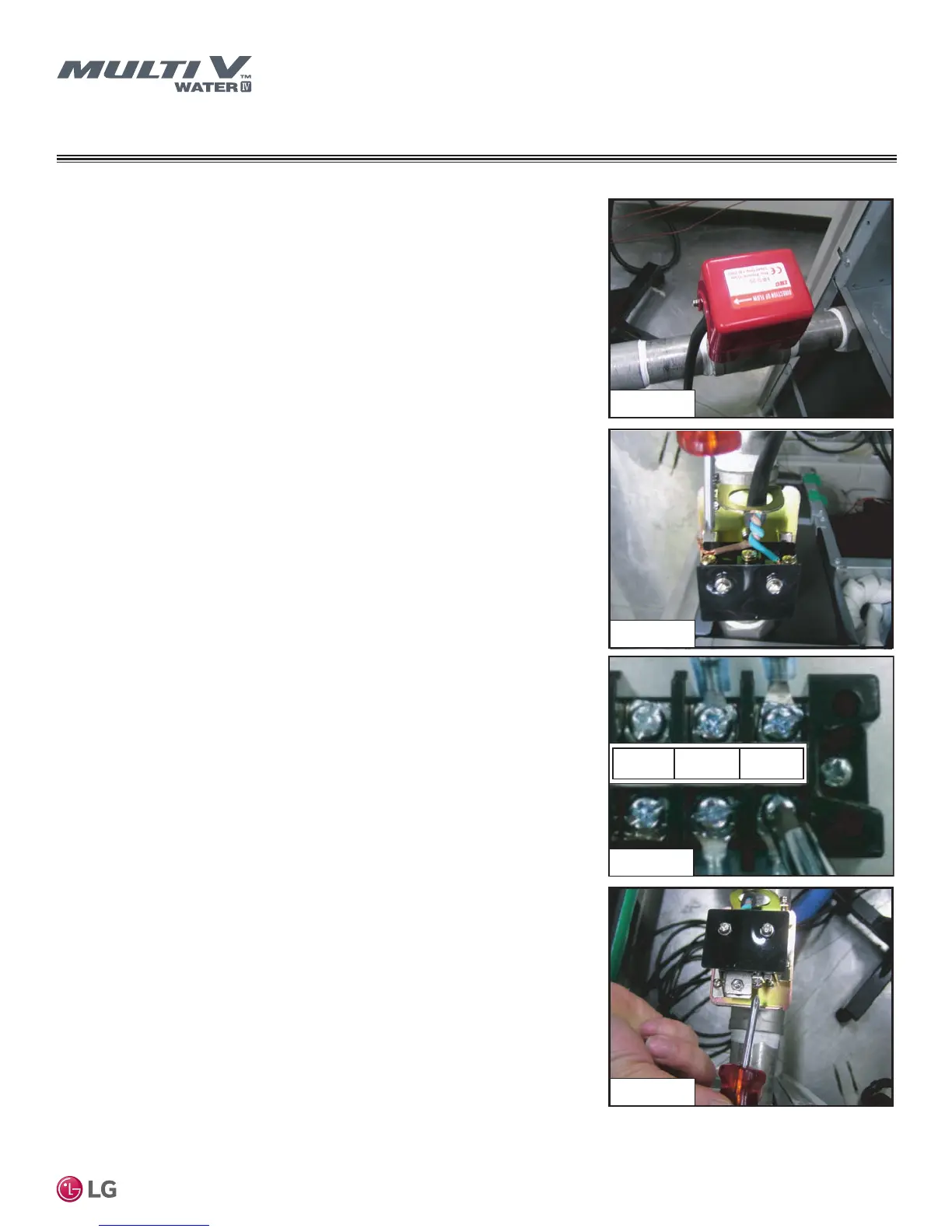
Flow Switch
• The flow switch must be installed at the horizontal pipe of the water source unit's
heat water-supply outlet. Verify the direction of the water flow before installation.
(Picture 1)
• Remove the jumper wire and connect to the communication terminals (4[A] and 4[B])
of the water source unit's control box. (Pictures 2, 3) Open the flow switch cover and
check the wiring diagrams before connecting the wires. Wiring methods can vary by
flow switch manufacturer.
• If necessary (and after consulting with an LG representative), use the flow rate
detection contact to adjust flow rate to within the minimum range. (Picture 4)
Minimum flow rate range of this product is 50%. Adjust the flow switch to the contact
point when the flow rate reaches 50%.(Minimum flow rate range is 50%; When
installing the Variable Water Flow Control Kit, set minimum water flow to 40% of
nominal flow rate.)
• If the product operates while the flow switch contact point is out of the
permitted range, it can result in performance deterioration or system failure.
• Use a normally-closed type flow switch.
Picture 1
Picture 2
Picture 3
Picture 4
Picture 3
4(N) 5(A) 5(B)
Picture 2
Picture 1

 Loading...

