10
PAHCMR000 AHU Communication Kit Installation Manual
Due to our policy of continuous product innovation, some specications may change without notication.
©LG Electronics U.S.A., Inc., Englewood Cliffs, NJ. All rights reserved. “LG” is a registered trademark of LG Corp.
Switch
Number
SW1
ODU Type
On
Single Comm.
Using Single Zone outdoor unit
Off
MULTI V Comm.
Using MULTI V outdoor unit
Control Type
On
Communication
Controlled by DDC through Modbus or LG centralized controller
Off
Contact signal
Controlled by DDC through Contact signal (AI, DI)
LG Centralized controller can only monitor status
DO Type
On
DO1 : High, DO2 : Middle, DO3 : Low
Off
DO1 : On/Off, DO2 : Defrost, DO3 : Alarm
4
Fan Speed
(TH. On/Off)
On
Fan Speed doesn’t change when TH. On/Off (Cooling/Heating)
Off
Change
Fan Speed change to LOW when Th. Off in Cooling Mode
Fan Speed change to STOP when Th. Off in Heating Mode
SW2
Reserved
-
--
Reserved
-
--
UI Setting
Off/Off
UI Setting #1
UI1 : Operation On/Off, UI2 : Heating/Cooling
UI3 : Forced Thermo On/Off, UI4 : Target air temperature
Off/On
UI Setting #2
UI1 : Operation On/Off, UI2 : Cooling only/Off
UI3 : Heating only/Off, UI4 : Forced Thermo On and Off
On/Off
-devreseR
On/On
-devreseR
SW3
Master/Slave
On
Slave mode
Off
Master mode
Master mode is default for single AHU Controller installation.
2/3
Operation mode
setting
Off/Off
Cooling or Heating operation mode is available
Off/On
Operation mode is Heating only (Heating / Fan)
On/Off
Operation mode is Cooling only (Cooling / Fan)
On/On
-devreseR
Reserved
--
SW4
Capacity
Setting
--
Refer to the capacity DIP switch setting table for details
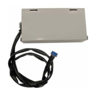
Communication Module
The default setting of all DIP switches is “off”
Notes :
1) Do not change reserved switches. Changing reserved switches may cause equipment malfunction.
2) If using group control, the maximum length of the group control cable is 164ft including remote controller wiring.
Fan speed
Status
Fixed
-
1
2
3
1
2
3/4
1
4
Heat Pump
Heating Only
Cooling Only
DIP Switch Item Setting Note
1~4
Setting the AHU DIP Switches
For the AHU Communications Kit to function properly, set the DIP switches as required by your system.
Figure 3: DIP Switches
Table 4: DIP Switch Settings.
AHU COMMUNICATIONS KIT INSTALLATION
DIP Switch Settings
 Loading...