14
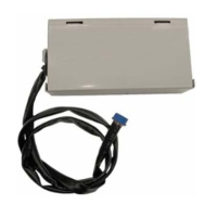
PAHCMR000 AHU Communication Kit Installation Manual
Due to our policy of continuous product innovation, some specications may change without notication.
©LG Electronics U.S.A., Inc., Englewood Cliffs, NJ. All rights reserved. “LG” is a registered trademark of LG Corp.
AHU COMMUNICATIONS KIT INSTALLATION
Wiring Diagram
Figure 6: PAHCMR000 AHU Communications Kit Wiring Diagram.
* Set the UI1, UI2, UI3, and UI4 ports DIP switches as appropriate for your system
** Set the DO1, DO2, and DO3 ports DIP switches as appropriate for your system
SW1
DO Type
On
DO1 : High
DO2 : Middle
DO3 : Low
Off
DO1 : On/Off ***
DO2 : Defrost
DO3 : Alarm
Fan speed
Status
3
SW2
UI Setting
Off/Off
UI Setting #1
UI1 : Operation On/Off
UI2 : Heating/Cooling
UI3 : Forced Thermo On/Off
UI4 : Target air temperature
Off/On
UI Setting #2
UI1 : Operation On/Off
UI2 : Cooling only/Off
UI3 : Heating only/Off
UI4 : Forced Thermo On and Off
3/4
UI1* UI2*
UI3*
UI4*
DO1** DO2** DO3**
*** This output can be used to start/stop an AHU single-speed fan
 Loading...