Chapter 6 Electrical Connections 33
Liebert.CRV Series Air Conditioner User Manual
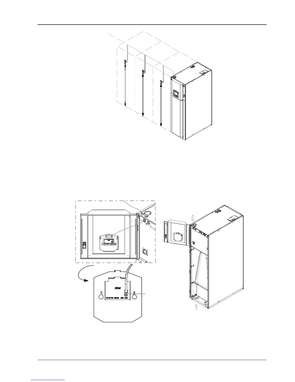
SENSOR CHAIN
1500 (59 in)
1500 (59 in)
1500 (59 in)
1.5m
1.5m
1.5m
Figure 6-6 Sensor chain configuration
Insert the rack temperature sensor connector in the temperature sensor port (CAN port as shown in Figure 6-7) at the
iCom interface. After cabling like shown in pictures to exit from the top or from the bottom of the unit, connect to first
probe, then from first to second one, from second to third one and so on, like a chain. Secure the temperature sensor
in front of the warmest heat source in the enclosure. Do not secure in front of a blanking panel. For this operation use
the support provided for each probe (see Figure 6-8). The sensors must be installed where lack of sufficient cooling
air is most likely. Due to air flow behavior (see Chapter 2 Unit Positioning), sometimes it would be better to
reconsider the layout, or particular attention must be taken positioning the sensors.
BOTTOM INLET
(possible with raised floor)
TOP INLET
FRONT VIEW
Top inlet
Bottom inlet (possible
with raised floor)
Front view
Cable connection of first sensor
Amplified
CAN port
Figure 6-7 Connection of temperature sensor