32 Chapter 6 Electrical Connections
Liebert.CRV Series Air Conditioner User Manual
Phase failure recognition
If one phase failes for 5s minimum, motor will be switched off (only by electronics, no potential separation), status
relay is released. If all 3 phases return to correct values, the motor will restart automatically within 10s ~ 40s.
The power supply for an external speed setting potentiometer is short-circuit protected.
Motor is overload-protected via motor current limitation.
Warning: Leakage current of the motor is 7mA roughly.
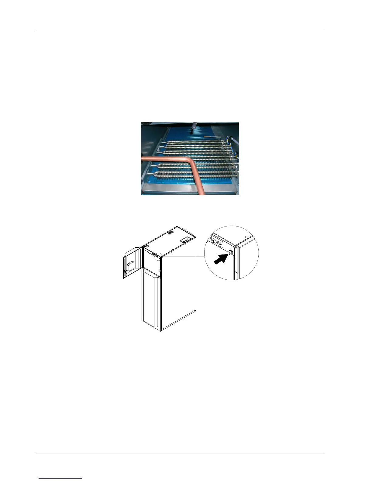
6.3 Protective Features Of Electrical Heaters
The electrical heaters with temperature sensor protection are shown in Figure 6-4.
Figure 6-4 Electrical heaters with temperature sensor protection
In case of over temperature of electrical heating, the temperature sensor checks it and the thermal protection turns off
the current. To reset the thermal protection push the bottom in front of the unit as indicated in Figure 6-5.
Figure 6-5 Resetting button
6.4 Temperature Probes Placed On Racks
Each unit is provided with at minimum three temperature probes (standard feature) and they can be up to ten. They
are located inside the unit, behind rear door (access to the fans panel rotating the three locks with the black key).
The sensors may be placed where desired or left coiled inside the unit. It is recommended that the sensor be routed
to the front of the heat load for the most accurate temperature reading. If the sensor is left inside the unit, ensure the
sensor and cable do not rest against the compressor or refrigerant lines. Doing so may damage the sensor. In sensor
chain configuration (see Figure 6-6), each temperature sensor monitors the temperature of the air entering the rack
equipment. The reading is used to control the operation of the unit. A standard position is at 1.5m in height, so the
sensor must be placed as shown in Figure 6-6, or the equipment will not operate properly.