Chapter 4 Refrigeration Connections 19
Liebert.CRV Series Air Conditioner User Manual
Chapter 4 Refrigeration Connections
This chapter introduces refrigeration connections of the Liebert.CRV air conditioner, including refrigeration pipeline
connections for air-cooled (A) units, vacuum creation and refrigerant charge, and refrigeration circuits.
Warning
Use only condenser unit design for R410A refrigerant.
The unit is designed both from top and bottom side.
4.1 Refrigeration Pipeline Connections For Air-Cooled (A) Units
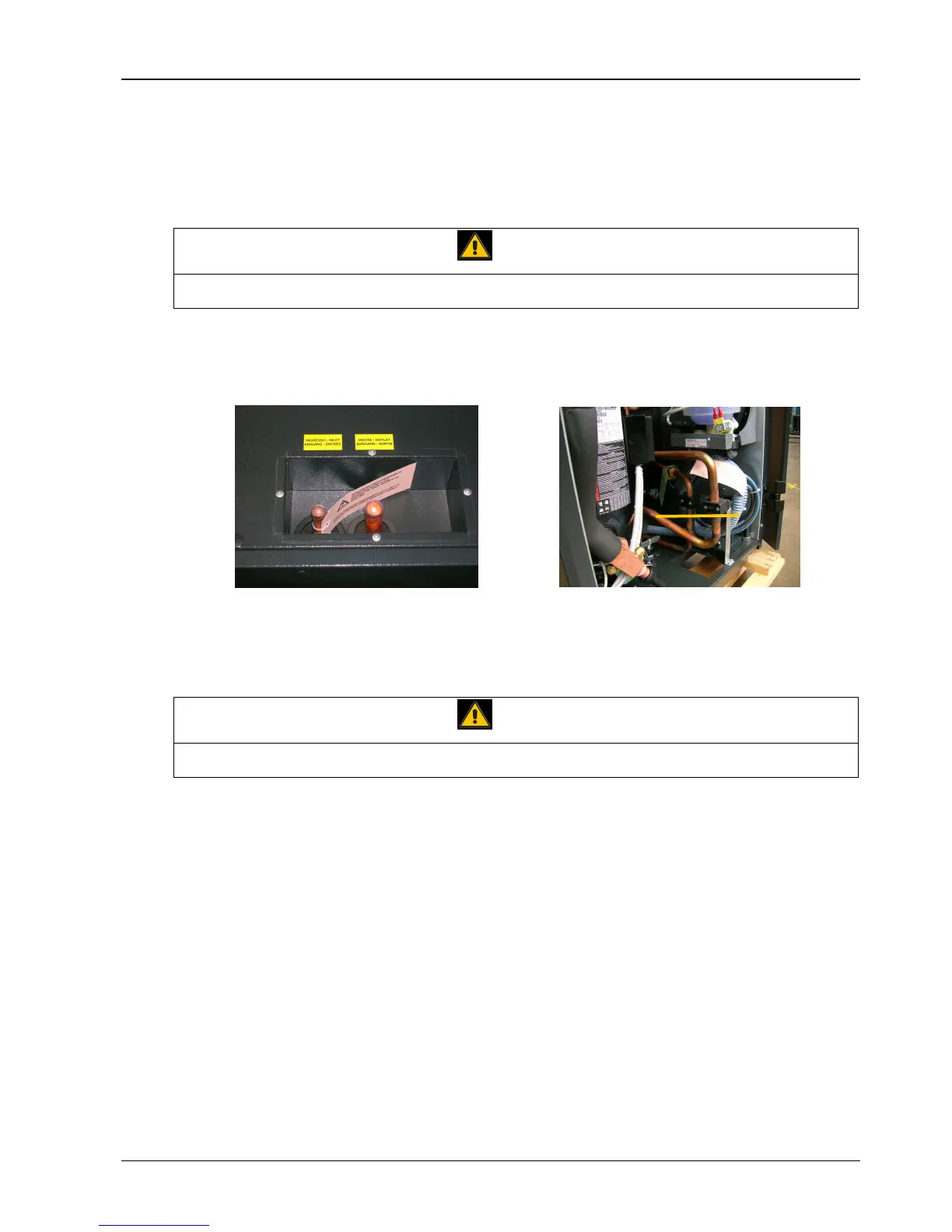
The refrigeration pipeline connections on unit top and bottom are shown in Figure 4-1.
Top refrigeration pipeline connections
Bottom refrigeration pipeline connections
(If you are using bottom ones, de-braze pipes across square dot line and
remove pipes to the top of the unit. Then braze new pipes to bottom.)
Figure 4-1 Refrigeration pipeline connections
The air condensing units are delivered with nitrogen pressurized at 2bar.
Warning
The discharge operation of the room unit pressurized with nitrogen (at 2bar) and the de-brazing of the bottoms from the
connections must be carried out as last operations, immediately followed by the connection and emptying of the whole system.
4.1.1 General Layout
The recommended pipe layout is shown in Figure 4-2, and the No. descriptions are as follows:
①: In soft or hard copper. The diameter required is stated in Table 4-2. If the installer intends to use pipes of a larger
diameter (e.g. for long winding runs) then consult Emerson services. Use refrigeration pipelines which are as short as
possible to minimize the total charge of refrigerant and the pressure drops. Lay the horizontal gas pipes with 1%
downward gradient towards the refrigerant flow.
②: Reduce the number of bends, which must be of large radius, to a minimum.
③: Insulate the piping as specified in Table 4-1. If the pipes are put next to electrical cables it is advised to insulate
them to avoid damage to cable insulation.
④: There must be a minimum separation of 20mm between the gas and liquid pipelines. If this is not possible insulate
both lines.
⑤: Support both horizontal and vertical pipes with vibration-damping clamps (which include rubber gaskets). Place
these every 1.5m ~ 2m.