REV : 8
REV DATE : 12/16
DPN002939
Page :1 /1
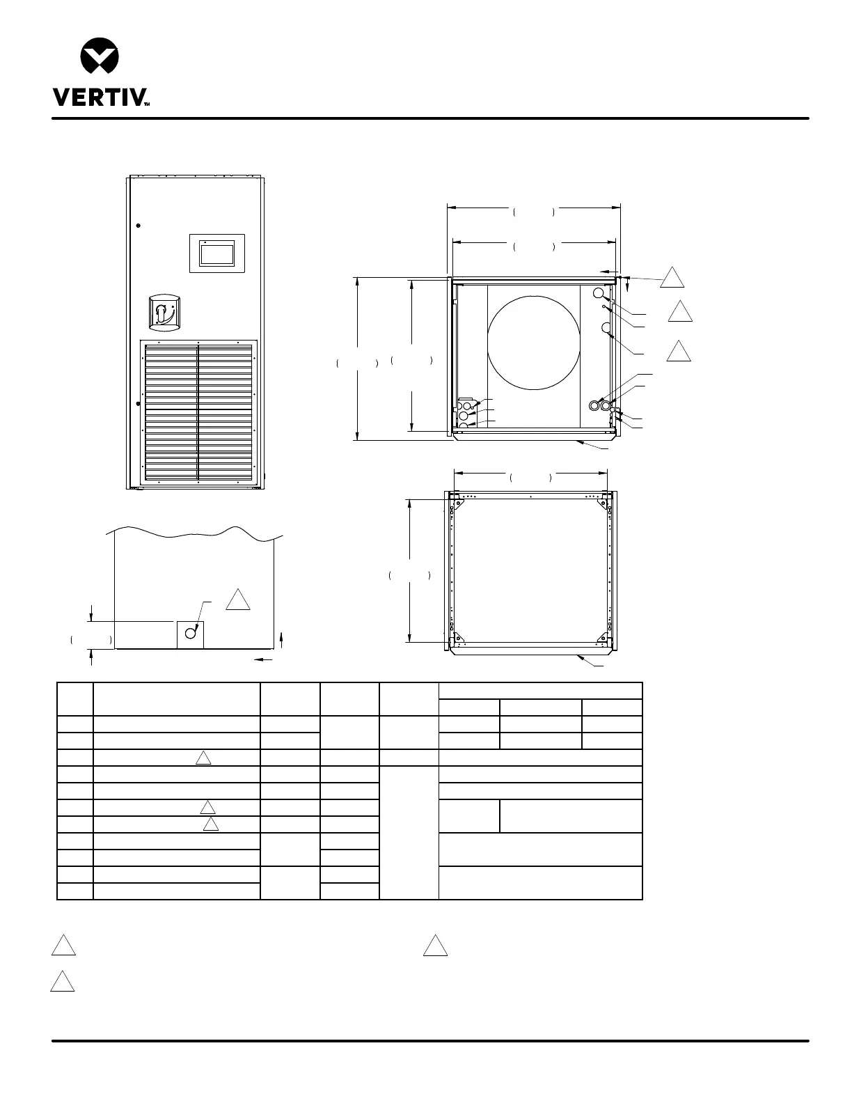
UPFLOW AIR COOLED MODELS
Form No.: DPN001040_REV4
PRIMARY CONNECTION LOCATIONS
LIEBERT PDX
LV1
ECS
LV2
FRONT VIEW
X
Y
O
TOP VIEW
32 5/8"
828mm
34 1/2"
876mm
FRONT OF UNIT
FRONT OF UNIT
28 9/16"
725mm
30 1/2"
775mm
TOP VIEW
G1
L1
E1
E2
HUM
Y
Z
RIGHT SIDE VIEW
CD
CDP
ECR
CONDENSATE DRAIN WITH PUMP
ELECTRICAL CONN. (HIGH VOLT)
ELECTRICAL CONN. (HIGH VOLT)
ELECTRICAL CONN. (LOW VOLT)
ELECTRICAL CONN. (LOW VOLT)
POINT DESCRIPTION X in. (mm) Y in. (mm)
1-1/2 (38)
31-1/4 (794)
25-5/8 (651)
1
7/8, 1-3/8, 1-3/4
7/8
Z in. (mm)
N/A
N/A
1-1/8
CONNECTION SIZE/OPENING in.
3/4" NPT FEMALE
1/2
1/4
SUPPLY AIR
DISCHARGE OPENING
Notes:
1. Drawing not to scale. All dimensions from rear corner of unit including panels
and have a tolerance of ± 1/2" (13mm).
2. Field pitch Condensate drain line a minimum of 1/8" (3mm) per 12" (305mm)
All units contain a factory installed condensate trap. Do not trap external to the unit.
Drain line may contain boiling water. Select appropriate drain system materials
The drain line must comply with local codes.
2
3
3
2
3
3
1
5 5/8"
143mm
3. Supplied on Dual Cooling Systems only.
4. Unit with front return shown. Bottom return with rear return floorstand also available.
5. All refrigerant & water piping connections are O.D. Copper except as noted.
30 3/16"
767mm
Duct
Flange
32 9/16"
827mm
Duct Flange