REV : 3
REV DATE : 2/17
DPN003004
Page :1 /1
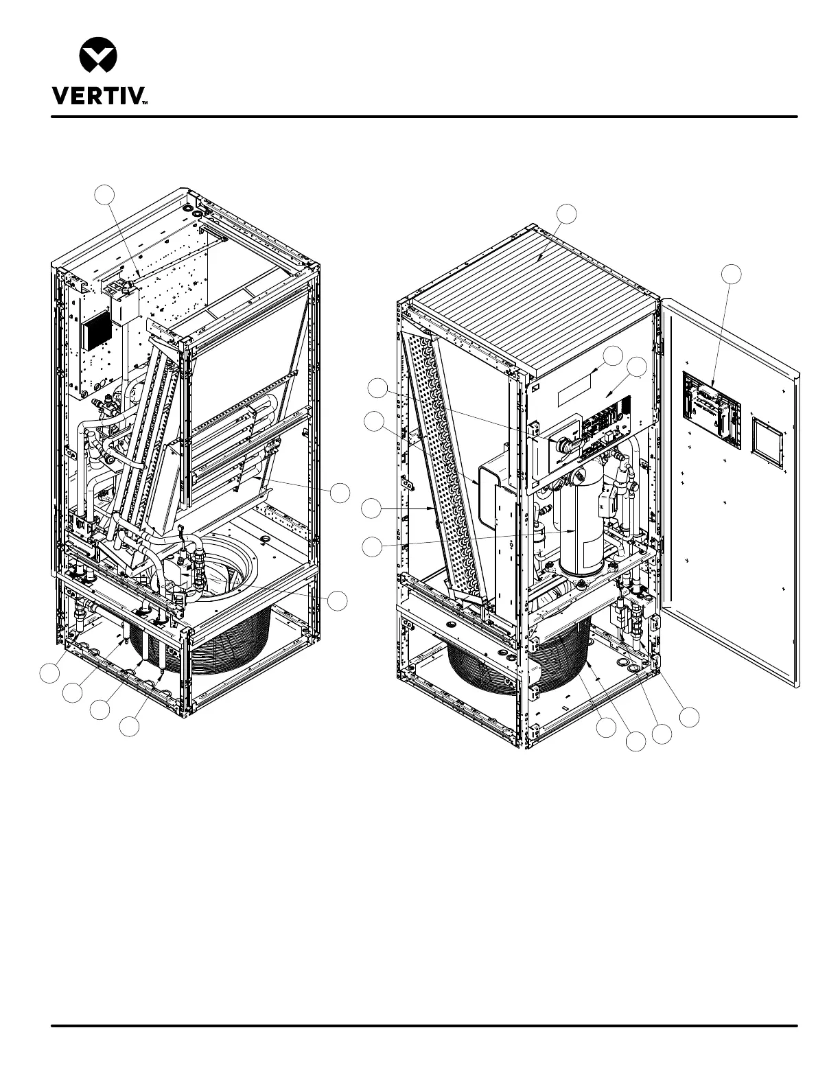
DOWNFLOW MODELS
Form No.: DPN001040_REV4
COMPONENT LOCATION DIAGRAM
LIEBERT PDX
1
2
4
5
6
7
9
10
11
12
REAR VIEW
FRONT VIEW
8
13
14
17
18
16
15
14
1. Liebert iCOM Control Display 11. Econ-O-Coil Valve - GLYCOOL™/Dual Cooling (optional)
2. Electric Box 12. Smoke Detector (optional)
3. Filter 13. Serial Tag
4. Evaporator Coil 14. Hot Gas Line (Air-Cooled) or Return Connection (Water/Glycol/GLYCOOL™)
5 Compressor 15. Liquid Line Connection (Air-Cooled)
6. Infrared Humidifier (optional) 16. Supply Connection (Water/Glycol)
7. Disconnect 17. Supply Connection (GLYCOOL™/Econ-O-Coil)
8. EC Fan 18. Return Connection (Econ-O-Coil)
9. Electric Reheat (optional) 19. Steam Gen Humidifier (option not shown, located to the left hand side of the Compressor)
Plate Condenser (optional)
3