REV : 3
REV DATE : 2/17
DPN003021
Page :1 /1
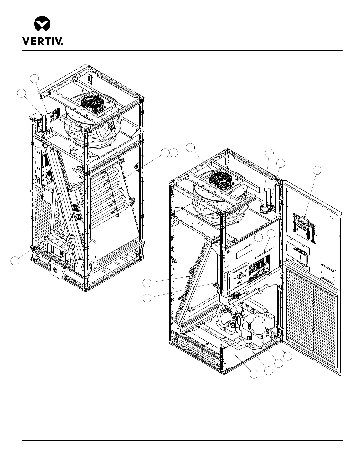
UPFLOW MODELS
Form No.: DPN001040_REV4
COMPONENT LOCATION DIAGRAM
LIEBERT PCW
REAR VIEW
8
10
FRONT VIEW
1
2
4
5
6
7
9
11
12
14
14
3
15
13
13
1. Liebert iCOM Control Display
2. Electric Box
3 Filter (partial filter shown for clarity)
4. Chilled Water Coil
5. Infrared Humidifier (optional)
6. Disconnect
7. EC Fan
8. Electric Reheat (optional)
9. Chilled Water Valve
10. Smoke Detector (optional)
11. Condensate Pump (optional)
12. Serial Tag
13. Supply Connection - Chilled Water
14. Return Connection - Chilled Water
15. Hot Water Reheat Coil
(option not shown, located in place of Electric Reheat)
16. Steam Gen Humidifier
(option not shown, located above Condensate Pump