REV : 3
REV DATE : 2/17
DPN003020
Page :1 /1
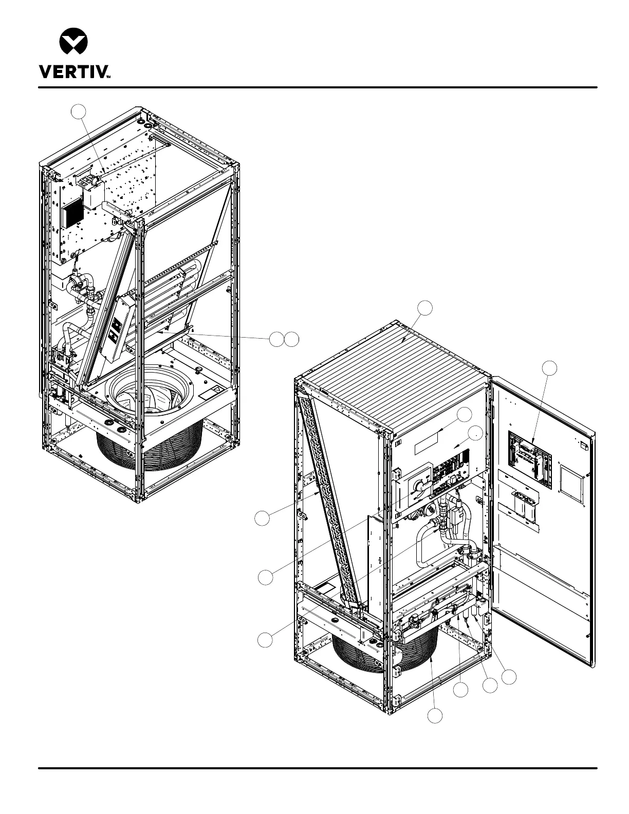
DOWNFLOW MODELS
Form No.: DPN001040_REV4
COMPONENT LOCATION DIAGRAM
LIEBERT PCW
1
2
4
5
6
7
8
9
10
FRONT VIEW
REAR VIEW
11
13
3
14
12
1. Liebert iCOM Control Display
2. Electric Box
3. Filter
4. Chilled Water Coil
5. Infrared Humidifier (optional)
6. Disconnect
7. EC Fan
8. Electric Reheat (optional)
9. Chilled Water Valve
10. Smoke Detector (optional)
11. Serial Tag
12. Supply Connection - Chilled Water
13. Return Connection - Chilled Water
14. Hot Water Reheat Coil (option not shown, located
in place of Electric Reheat)
15. Steam Gen Humidifier (option not shown, located
to the left of the Chilled Water Valve)