www.lifebreath.com
Page 3
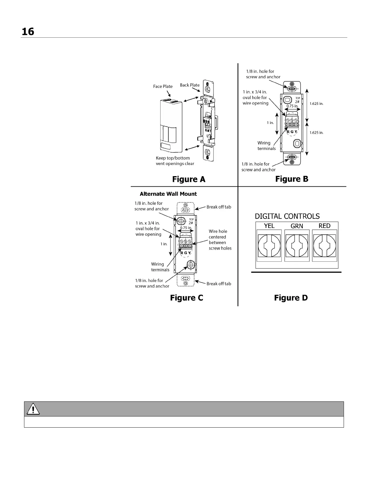
MAIN WALL CONTROLS
The 99-BC02, 99-BC03, 99-BC04 ventilation controls may either be installed onto a flush mounted electrical switch box or
surface mounted onto a wall. Only one main control should be installed into a ventilation system.
Installation:
1. Carefully separate the face plate
and the back plate by firmly
pulling it apart. Keep the
top/bottom vent openings clear
(figure A).
2. Position the back plate in the
desired location on the wall and
mark the wall for the desired
screw holes (figure B).
3. For mounting the main control
without a Decora plate, break off
the top and bottom tabs than
position the back plate in the
desired location on the wall and
mark the wall for the desired
screw holes (figure C)
4. Remove the back plate from the
wall and mark the hole for the
wires centered between the two
screw holes (figure B or C).
5. Drill two 1/8 in. holes for the
screws and wall anchors and drill
one 1 in. x 0.75 in. hole for the
wires.
6. Pull the 3 wire 20 gauge (min.),
100 ft length (max.), through the
opening in the wall.
7. Connect the wires to the R, G, and
Y terminals on the back plate
(figure B or C).
8. Using the two supplied screws and
anchors, install the back plate on
the wall.
9. Attach the face plate to the back plate (figure A).
10. Connect the 3 wire 20 gauge (min.), 100 ft length (max.), to the RED, GRN, and YEL terminal on the Digital Controls
terminal strip on the Aircom circuit board (figure D).
Use care when separating or attaching the face plate to avoid damaging the contact pins.