Netlink Installation and Operation Manual
8 9
Installation and Operation
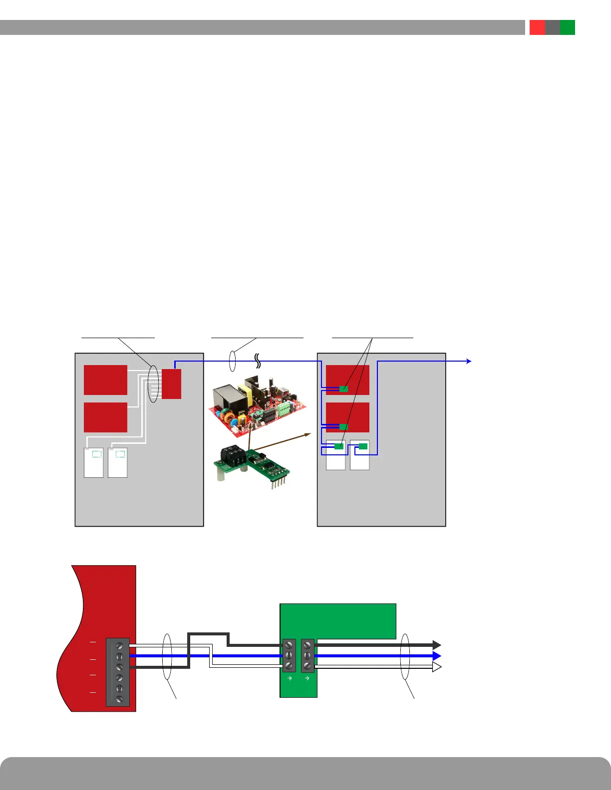
1.3.9 RS485 Port (NLX only)
The RS485 port allows connection of up to 16 additional
LSP devices. The connected devices must be Generation
2 FPO or M8 modules with the optional RS485 module
(RSMOD) installed. See figure 1.9.
RS485 Terminals:
A Signal Line A
B Signal Line B
GND Ground
There are two sets of RS485 terminals which may be used
interchangeably to allow two branches from the NLX. The
A, B, and GND terminals from the NLX must be connected
to the A, B, and GND terminals of the monitored device.
The next device in the chain should connect from the sec-
ond set of RS485 terminals on the monitored device to the
next device in the chain and so on. The final device in the
chain must have a termination resistor installed between A
and B on the second RS485 terminal set.
Wiring for the RS485 buss must be a single 24AWG twisted
pair with drain wire and shield with 120 ohm impedance.
The maximum total combined wire length is 2000ft.
i Note: Failure to use the proper wire type, connection
menthods, and termination resistor may prevent proper
communication.
Devices connected via RS485 must each be set to a unique
address. See the FPO or M8 manual for addressing infor-
mation
NLX
GND A B GND A
RS485 RS485
B
RSMOD
A
B
A
B
RS485 Buss
Continues To Next
RSMOD
24AWG Twisted Pair
with Shield
24AWG Twisted Pair
with Shield
GND
A
B
NLX
FPO
FPO
8 SPI Ports
Local Connections
Within 12 Feet of NLX
RS485 Buss
Remote Connections
Up to 2000 Feet From NLX
RSMOD Module
Daughter card option on new
Gen2 FPO, M8 coming QIII
FPO
FPO
RS485 Buss
Continues To Next
Enclosure
M8 M8
M8 M8
RSMOD RS-485 option module
connects to
(Gen2) FPO, M8
Figure 1.9 - RS485 Wiring

 Loading...