Lighthouse REMOTE 2012, 3012, 5012, 3102, 5102 Operating Manual
3-6 248083201-1 Rev 6
Table 3-2 J10 without Status Data Connector Pinouts
* If the application allows, VLOOP and VPWR may be connected to
the same source. In that case, the VPWR is +15VDC to +30VDC.
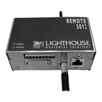
Included with the instrument is a plug to connect the J10 connector to
your Facilities Monitoring System.
Figure 3-9 J10 Connector With Plug Attached
Pin Number Signal Range
1 Chan 1 1) 4-20mA particle count levels
2) 2mA Service Alert level
2 Chan 2 1) 4-20mA particle count levels
2) 2mA Service Alert level
3 * VLOOP +15VDC to +30VDC
4 Ground
5N/A -
(Figure 3-5)
6 Ground
7 * VPWR +6VDC to +30VDC
8 External
Alarm (-)
Continuity with Pin 9 if ALARM.
9 External
Alarm (+)
+40VDC at 1A maximum