Getting Started
248083201-1 Rev 6 3-5
4. Attach tubing from external vacuum source to the barbed fitting on
the bottom of the unit.
Installing an
Isokinetic
Probe
An Isokinetic probe can be attached directly to the unit. Screw the
probe directly onto the inlet.
Figure 3-8 Installing Probe Directly on Barb
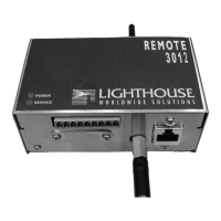
Data Port Connector J10 on the bottom of the instrument is used to communicate
with your Facility Management System. Signals at this port include two
4-20mA data channels, an external alarm channel, power and ground.
Table 3-1 J10 with Status Data Connector Pinouts
* If the application allows, VLOOP and VPWR may be connected to
the same source. In that case, the VPWR is +15VDC to +30VDC.
Pin Number Signal Range
1 Chan 1 1) 4-20mA particle count levels
2) 2mA Service Alert level
2 Chan 2 1) 4-20mA particle count levels
2) 2mA Service Alert level
3 * VLOOP +15VDC to +30VDC
4 Ground
5 Status (if
signal is
available -
Figure 3-4)
1) 4mA: no Alarm, no Service Alert
2) 12mA: Channel overflow Alarm
3) 20mA: SERVICE Alert
6 Ground
7 * VPWR +6VDC to +30VDC
8 External
Alarm (-)
Continuity with Pin 9 if ALARM.
9 External
Alarm (+)
+40VDC at 1A maximum