705iR User Manual
3 | 705iR User Manual
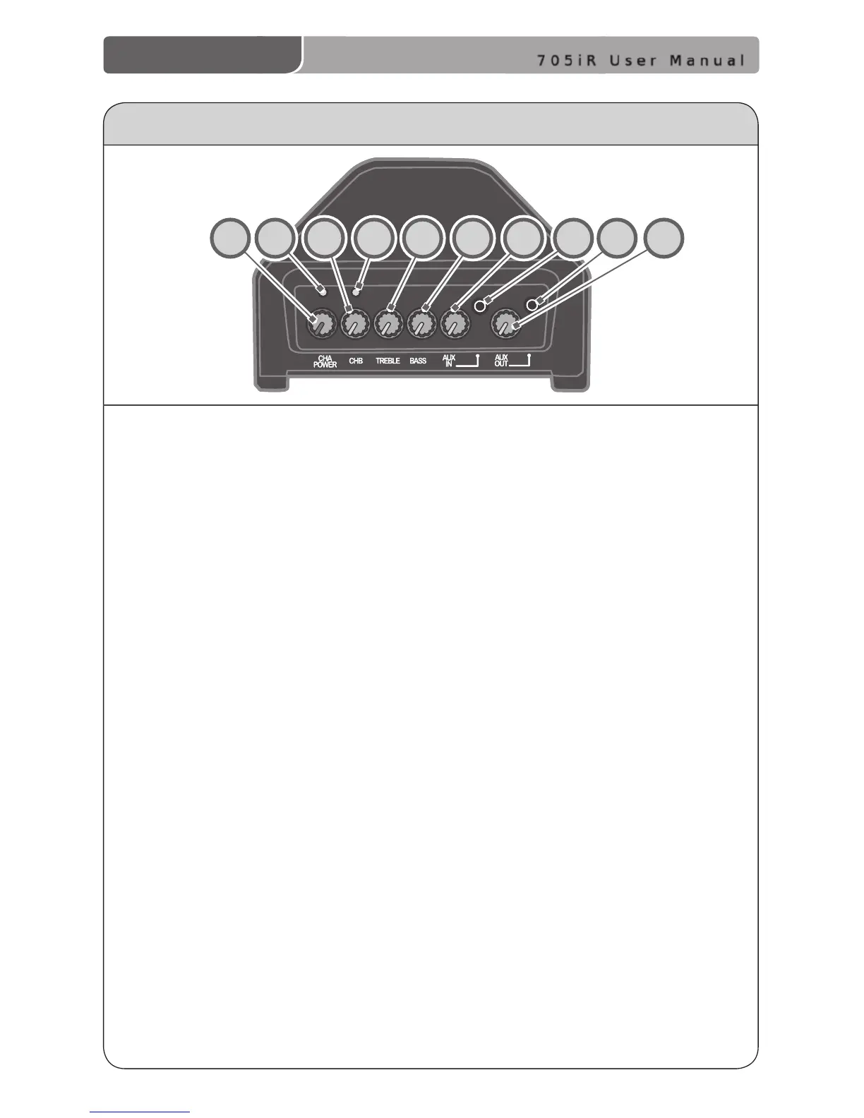
705iR CONTROLS AND CONNECTIONS
Top Panel
1. CH A POWER: This knob turns on
the power for the 705iR and
controls the Channel A volume.
We recommend using Channel A if
you are using a single microphone
for your system. Turn the knob
clockwise to increase volume.
2. The LED light located above the
CH A POWER knob turns red
momentarily when the system
power is turned ON.
When a transmitter/microphone
set to Channel A is turned on, the
Channel A LED glows green to
indicate your transmitter’s signal is
being received by the amplier.
3. CH B VOLUME: This knob controls
the volume for Channel B. You must
rst turn the 705iR ON with the
CH A POWER knob, then turn the
CH B VOLUME knob clock-wise to
increase volume. Use Channel B
when using a second microphone.
4. The LED above CH B VOLUME
turns green to indicate a signal is
being received from a microphone/
transmitter set to Channel B.
5. TREBLE: This knob controls the
high-frequency sound of the 705iR.
Classroom Audio System.
6. BASS: This knob controls the low-
frequency sound of the 705iR.
7. AUX IN VOLUME: This knob
controls the volume level of an
external audio source that is
plugged into the AUX IN jack. An
example would be a computer, iPod,
or CD player.
8. AUX INPUT JACK: This 3.5 mm jack
is used to connect to an external
audio source.
9. AUX OUTPUT JACK: This 3.5 mm
jack provides a line-level audio
output that can be connected
to a personal FM system or tape
recorder.
10. AUX OUT VOLUME: This knob
controls the audio level going to
external equipment when plugged
into the AUX OUT jack. For example,
a personal FM transmitter or tape
recorder.
1 2 3 4 5 6 7 8 9
10