Link HD System Manual
Document # -HD System Man Iss 1.1 Issue 1.1 06/11/2007
Page 14 of 31
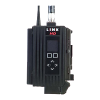
2.4 L2132 Receiver
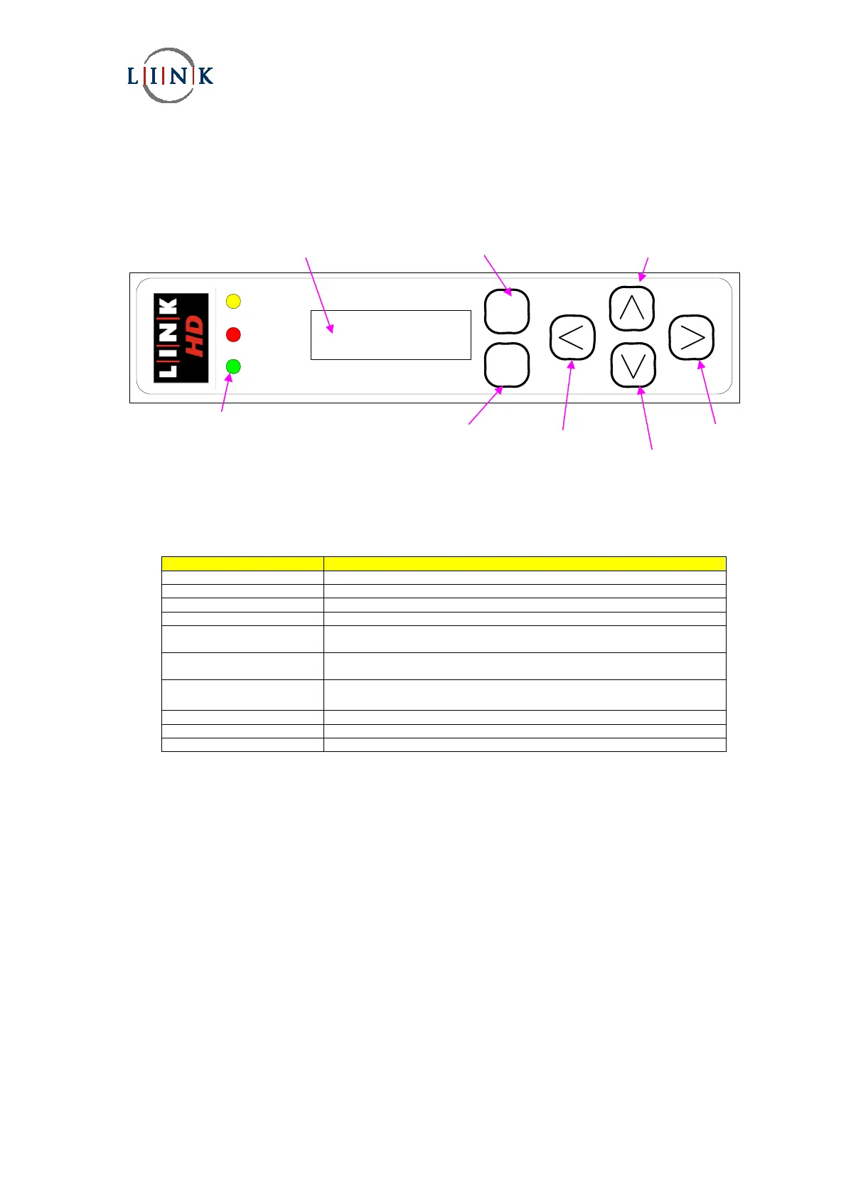
The diagram below shows the function of the front panel controls and displays necessary to operate the receiver.
STATUS
ALARM
POWER
L2100 DIVERSITY IRD - Ultra Low Delay
2.4.1 Controls
The operation of the receiver is through the six membrane buttons on the front panel of the receiver. These allow the
operator to navigate through the various menus.
Control/Display Function
Enter button Selects the currently selected parameter.
Exit button Cancels any parameter changes and Escapes to higher menu.
Up button Allows upward navigation in a sub menu.
Down button Allows downward navigation in a sub menu.
Left button Allows movement to the left when changing parameters within a menu
setting.
Right button Allows movement to the right when changing parameters within a menu
setting.
LCD window
Displays menu settings and system status
Status LED (yellow) When lit, the receiver is locked to a signal.
Alarm LED (red) When lit, an alarm has been detected.
Power LED (green) When lit, power is applied to the receiver.
Left
button
Enter
button
LED indicators
Liquid crystal display
Exit button
Down
button
Right
button
Up
button