Link HD System Manual
Document # -HD System Man Iss 1.1 Issue 1.1 06/11/2007
Page 19 of 31
2.4.4 Connectors
All connectors are mounted on the rear panel of the unit.
ASI In
CH 1
CH 2
ASI Out
SDI Out#1 SDI Out#2
F/Lock
RF #1
RF #2
Remote / Data
Camera Control
Connector type Legend Description
BNC 75 bayonet socket RF1 & RF2 RF input, Power Out to the L3020.
Max input level -20dB
9-way D-sub socket Remote/Alarm/Data RS232 remote control and User data port
Alarm signalling
BNC 75 bayonet socket SDI Out #1 & #2 HD-SDI Video output (SMPTE 292M)
BNC 75 bayonet socket Frame lock Delays the output signal by up to 40ms to lock
the video frames to an external reference.
NB – colour sub carrier is not locked.
BNC 75 bayonet socket ASI Output ASI output from demodulator
BNC 75 bayonet socket ASI Input ASI input for remux / diversity operation
5-way XLR Ch1 & Ch2 Each XLR can supply an analogue stereo pair or
single digital AES-EBU outputs
6pin LEMO Camera Control Interface to L1255 CC Data Transmitter
IEC socket* Mains 110 –220VAC Mains power input
4-way XLR panel mounted
plug*
DC in DC power input 9VDC – 32VDC
* Standard configuration is for IEC mains input. The DC input is optional and replaces the IEC socket.
2.5 L1255 Wireless Camera Control Unit (CCU) Interface
2.5.1 Controls and Setup
The L1255 has no operator controls as all configuration is from the L2132 Receiver.
Please see Section 2.4.2.7 for details of the CCU Menu. Three LEDs on the front panel indicate the status of the unit.
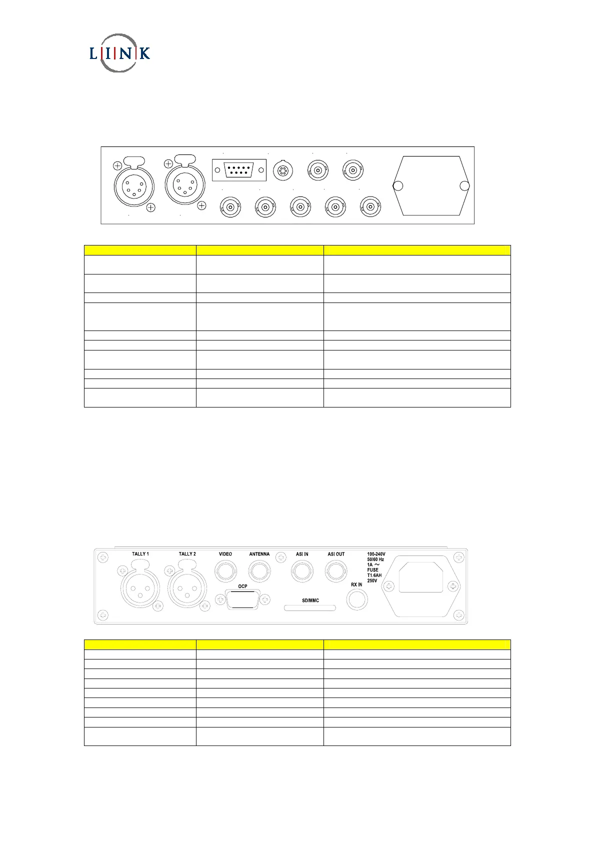
2.5.2 Connectors
Connector type Legend Description
BNC 50 bayonet socket Antenna RF output to UHF antenna
9-way D-sub socket OCP RS232 connection to OCP
BNC 75 bayonet socket Video Not Used
BNC 75 bayonet socket ASI Output Not Used
BNC 75 bayonet socket ASI Input Not Used
3-way XLR Tally 1 & Tally 2 Future use for tally input
6pin LEMO Rx In Interface to L2132 Reciever
IEC socket* Mains 110 –220VAC Mains power input
4-way XLR panel mounted
plug*
DC in DC power input 9VDC – 32VDC
* Standard configuration is for IEC mains input. The DC input is optional and replaces the IEC socket.