Link HD System Manual
Document # -HD System Man Iss 1.1 Issue 1.1 06/11/2007
Page 26 of 31
3.4 L2132 Receiver
3.4.1 Input / Output Connections
3.4.1.1 RF1 and RF2 inputs
Diversity input, antenna 1 to RF 1 and antenna 2 to RF2
UHF input when used with L3020 - 160Mhz to 910MHz.
Receiver sense limit –80dBm
Receiver overload limit –20dBm
+20VDC output to power up converter limited to 400mA per connector
Short circuit protected
75 BNC type chassis connector
3.4.1.2 Frame lock input
Composite Black and Burst input for timing reference.
Future units will support HD tri-level sync reference input.
Delay increased by 0 – 40ms
75 BNC chassis mounted connector
3.4.1.3 SDI Video out
SDI #1 and SDI#2. Two independent SDI outputs.
75 BNC chassis mounted socket for HD-SDI (SMPTE 292M) video output.
3.4.1.4 ASI out
ASI output from the demodulator for decoding by external MPEG2 HD Decoder.
75 BNC chassis mounted socket.
3.4.1.5 ASI Input
ASI input to the MPEG2 HD decoder. Selected via the Unit/Mode/ASI menu.
75 BNC chassis mounted socket.
3.4.1.6 Data/Remote/Alarm
A ‘D’ Type sub connector that is used for RS232 data output, firmware download and alarm outputs.
9way ‘D’ Type Chassis mounted socket
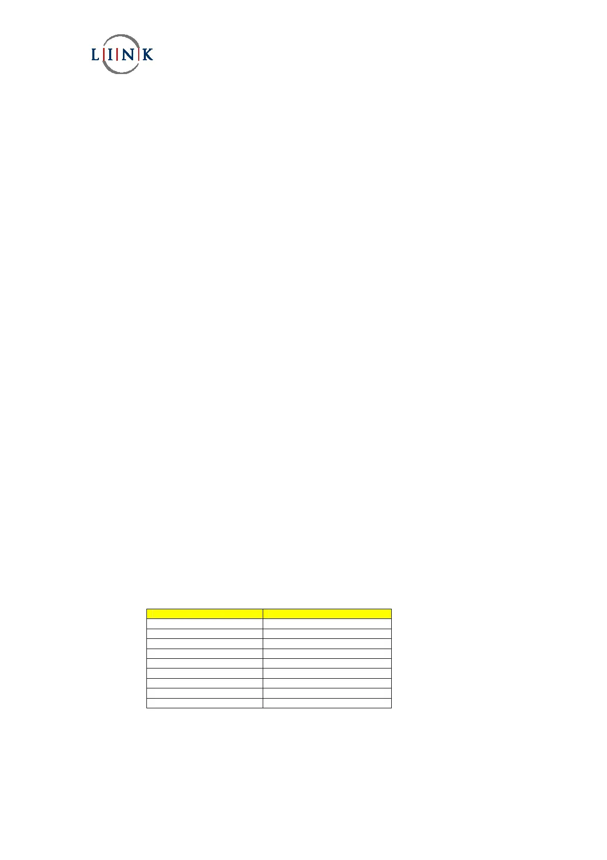
‘D’ Type Conn Function
Pin 1 Relay normally closed
Pin 2 Remote TX
Pin 3 Remote RX
Pin 4 Data in (diagnostic mode)
Pin 5 Data /Remote Gnd
Pin 6 Relay normally open
Pin 7 Remote TX enable
Pin 8 Data out
Pin 9 Relay common