Link HD System Manual
Document # -HD System Man Iss 1.1 Issue 1.1 06/11/2007
Page 12 of 31
2.1.4 L1403 Connector Interface
Top Panel Connector RF out N Type Male 50 ohm connector.
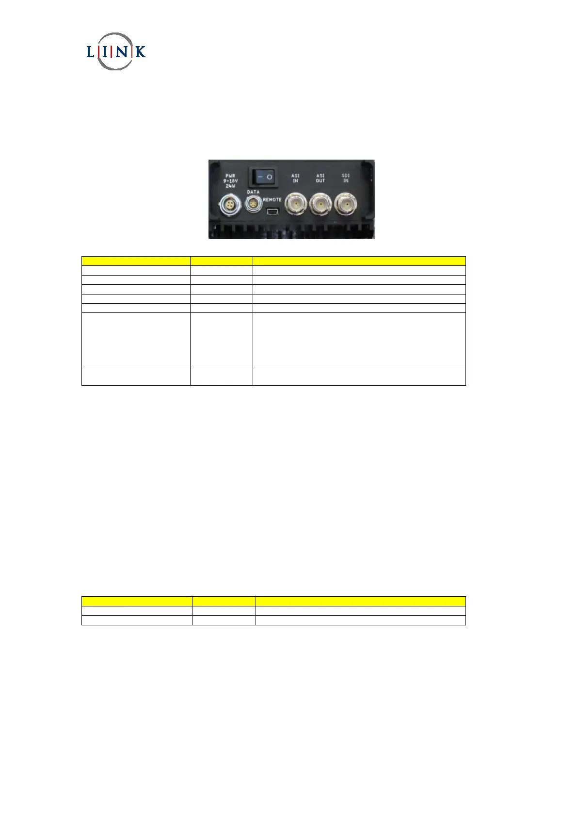
Lower Panel Connectors Position of panel connectors on the L1403 transmitter.
Connector type Legend Description
BNC 75 bayonet socket SDI In HD-SDI (SMPTE 292M)
BNC 75 bayonet socket ASI OUT DVB-ASI – output from the MPEG2 encoder
BNC 75 bayonet socket ASI IN DVB-ASI – into the Remux
USB REMOTE USB interface – future use
6 way LEMO DATA RS232 connection for Link Control
4 way LEMO PWR External 12V battery supply if rear ‘clip on’ battery is not
used.
It is also possible to take power from the ‘clip on’ battery.
Care must be taken to ensure that the ‘clip on’ battery on
the rear of the L1403 is not ‘back fed’ by an external
battery or power supply.
Power Switch Used to control the L1403/L1420 when supplied from the
rear ‘clip on’ battery.
Please see Section 3.1.2 for connector pinout details.
Please see Section 3.1.2.5 for detailed operation of the power switch.
2.2 L1420 Camera Controller / Data Receiver – Optional
All configuration of the camera controller is via the main L1403 LCD display and operators menu. :- Setup/Camera
Control/Cam Type.
The only functions that require to be configured are :-
Camera Type - Thomson (LDK6000)
Sony (HDC1500)
Ikegami
Frequency - Dependant upon the configuration of the UHF radio, please contact Link for details.
The following leads are supplied for connection between the camera controller (CC Data connector) and camera head.
Thompson- LDK6000 L0016
Sony L0017
Connector type Legend Description
4 way LEMO Tally Connection to external Tally light – future design
6pin LEMO CC Data Serial control data to camera head.
Please see Section 3.2.1.1 for cable and connector pinout details.