Pin 2 Left Line - (Return)
Pin 3 GND
Pin 4 Right Line + (Line)
Pin 5 Right Line - (Return)
3.4.6 DC Power
L1500 ~28W 12V DC nominal (10V minimum, 18V maximum)
Power dependent upon frequency of L1510, RF output power and camera control options.
Performance is degraded below 11.0V.
Chassis Socket Connector :- LEMO ECG1B304CLV
Mating Cable Plug :- LEMO FGG1B304CLAD62Z
Link Cable Assembly– flying leads :- L0003
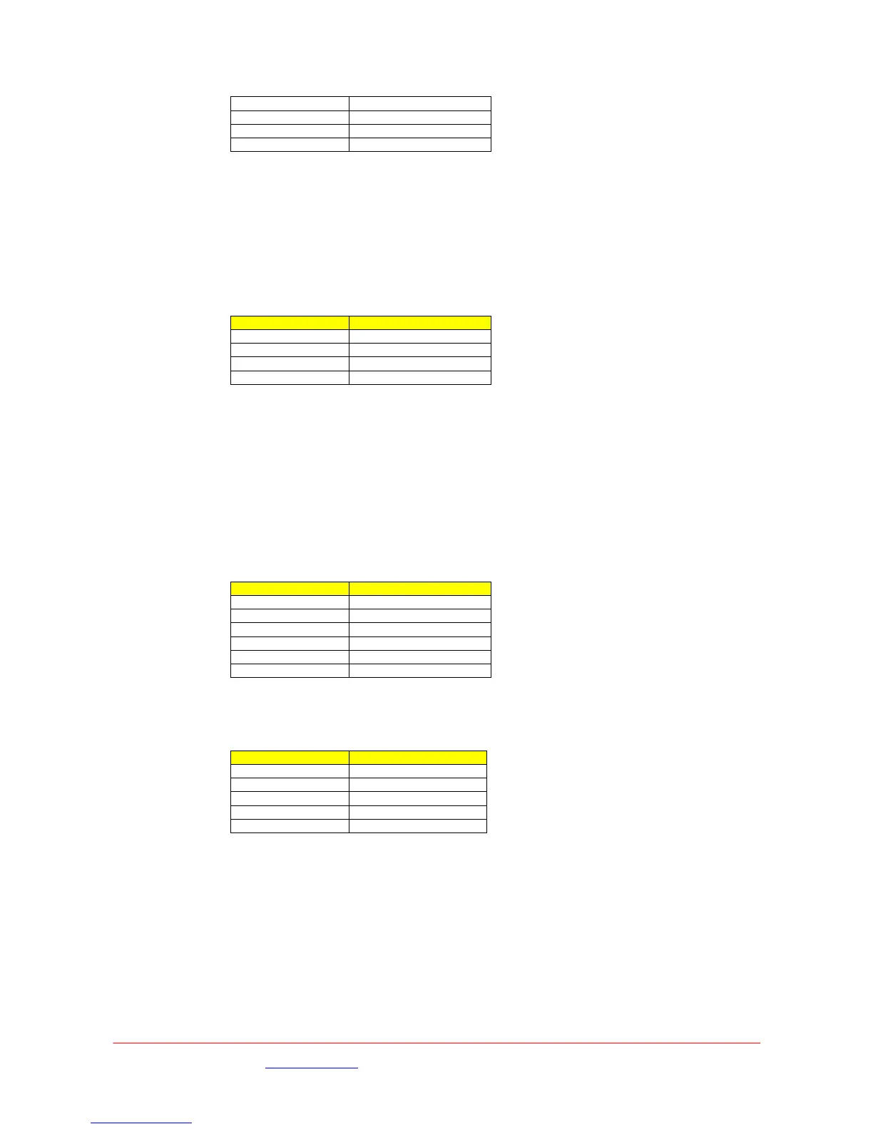
LEMO Pin Function
1 GND
2 GND
3 +12V supply
4 +12V supply
3.4.7 RF
100mW into 50Ω – switchable. 10, 50 ,100 and 250mW.
Note:- 250mW is for FCC use only.
50Ω chassis mounted ‘N’ type bulkhead socket.
3.4.8 RS232 Data & Control Port
The six pin connector provides the RS232 input / output of both the User Data and also Remote
Control of the transmitter unit.
Chassis Socket Connector :- LEMO EEF0B306CLV
Mating Cable Plug :- LEMO FGG0B306CLAD52Z
LEMO Pin Function
Pin 1 Tx Data (output)
Pin 2 Rx Data (input)
Pin 3 0v
Pin 4 Tx Control (output)
Pin 5 Rx Control (input)
Pin 6 0v
3.4.9 USB Data Port
A USB2 ‘Mini B’ style connector is to allow for serial communication with the unit.
Chassis Socket Connector :- Molex 67503-0020
USB Pin Function
Pin 1 Vbus
Pin 2 D-
Pin 3 D+
Pin 4
Pin 5 0V
Images are for illustration only and may differ from components supplied
Link Research Ltd www.linkres.co.uk Support UK/Europe + (44) 1923 474099 USA +(1)9786715700
Page 13 of 31 CL140045 Issue C Link L1500 Series System Manual
 Loading...