Camera Control
The return data from the camera is sent via the ‘User data’ and passed back to the the Data
transmitter.
Connector - LEMO 6pin socket EEF.0B.306.CLL
‘Lemo’ Type Function – RS232 Function – RS485
Pin 1 Rx Data (input) RS485
Pin 2 Tx Data (output)
Pin 3 0v 0v
Pin 4 Rx Remote (input) RS485
Pin 5 Tx Remote (output)
Pin 6 0v 0v
Mechanical
Height 44mm, Width 210mm, Depth 375mm - including rear panel connectors
Small form 1U, ½ width 19” rack mount
~1.7kg weight
Ambient 0ºC to +40ºC
Power
AC input option 100VAC to 240VAC 50Hz to 60Hz
DC input option 10VDC to 32VDC (-ve chassis earth)
20Watts excluding the downconverter requirements.
50Watts max allowing for downconverters and cables.
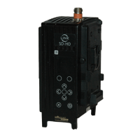
6 L3070/50 DownConverter (Base)
The Link Downconverter allows for the remote placement of the antenna from the receiver. It receives
the signal at the transmit frequency and downcoverts to a UHF signal 110-860MHz. This UHF signal
can then be fed, either through coax, triax or through a Link UHF Fibre system depending on the
distance to the receiver. Power is fed through the BNC coax from the receiver.
Note – the L3020 has been replaced by the L3070
The L3070/50 with filter is supplied with a +3dBi vertically polarised omni-directional antenna;
alternatively 6dBi vertically polarised 180° directional antenna which is available from Link Research
Ltd. Antennas should be co-located in pairs for optimised performance, allowing two areas of coverage
using the 4 channel Diversity receiver L2134. Greater coverage can be obtained by using Link
Research unique cellular diversity approach, contact support for information.
The down converter is supplied with a universal bracket for pole mounting. For temporary
installations, tie wraps may be used; for permanent installation U-bolts should be used.
Whichever method of mounting is used, it must be capable of supporting the weight of the unit and
the coaxial down lead. The two downconverters should be co-located to cover a specific area,
typically the are placed about 50cm apart, although this is not critical.
No other connections are required as the unit is powered from the receiver via the RF down lead.
Images are for illustration only and may differ from components supplied
Link Research Ltd www.linkres.co.uk Support UK/Europe + (44) 1923 474099 USA +(1)9786715700
Page 23 of 31 CL140045 Issue C Link L1500 Series System Manual
 Loading...