BNC 75Ω bayonet socket F’lock Delays the output signal by up to 40ms to
lock the video frames to an external
reference.
NB – colour sub carrier is not locked.
BNC 75Ω bayonet socket ASI Output ASI output from demodulator
BNC 75Ω bayonet socket ASI Input ASI input for decode operation
5-way XLR Ch1 & Ch2 Each XLR can supply an analogue stereo
pair or single digital AES-EBU outputs
6pin LEMO Camera Control Interface to L1255 CC Data Transmitter
IEC socket* Mains 110 –220VAC Mains power input
4-way XLR panel
mounted plug*
DC in DC power input 9VDC – 32VDC
* Standard configuration is for IEC mains input. The DC input is optional and replaces the IEC socket.
5.5 L2132/4 HD/SD Demodulator/Decoder Description and Specification
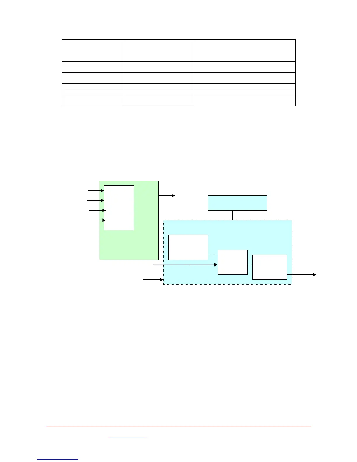
Block Diagram for L2134
LNB
Power
And
Interface
Input
Selector
RF1
ASI out
HD-
SDI
4 i/p Tuner Card
and Input Selector
CL132090
Front Panel Display B
CL130000
RF3
RF4
ASI in
SD/HD
DECODER
Main Board
CL131950
HD/SDFramelock
MRC Diversity
Demod
LMS/ DVB
RF2
5.6 Input / Output Connections
RF1 RF2 RF3 RF4 inputs
Diversity input, antenna 1-4 to RF 1-4 respectively
UHF input when used with L3020 - 110Mhz to 860MHz.
Receiver sense limit –80dBm
Receiver overload limit –20dBm
+20VDC output to power up converter limited to 400mA per connector
Short circuit protected
75Ω BNC type chassis connector
Frame lock input
SD Mode :- Composite Black and Burst input for timing reference.
HD Mode:- Support HD tri-level sync reference input.
Delay increased by 0 – 40ms
75Ω BNC chassis mounted connector
Images are for illustration only and may differ from components supplied
Link Research Ltd www.linkres.co.uk Support UK/Europe + (44) 1923 474099 USA +(1)9786715700
Page 21 of 31 CL140045 Issue C Link L1500 Series System Manual
 Loading...