Images are for illustration only and may differ from components supplied
Link Research Ltd www.linkres.co.uk Support UK/Europe + (44) 1923 474099 USA +(1)9786715700
Page 25 of 31 CL140045 Issue C Link L1500 Series System Manual
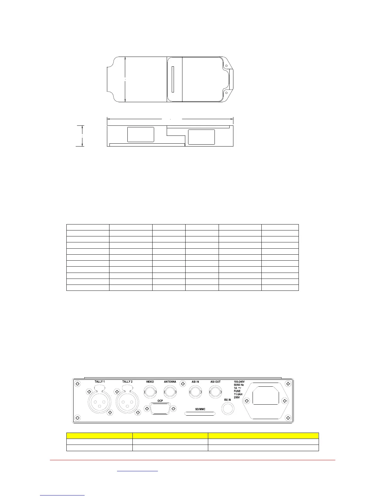
Height 240mm including connectors, width 70mm, depth 55mm including base plate and pole bracket.
Weight 0.8kg.
70.00 mm
32.50 mm
195.84 mm
The unit is provided with a mounting plate that can be attached using four M3 fixings or alternatively
ote: The 7GHz downconverters are larger and with connectors are 270mm.
ded from the L2132/4 receiver at a nominal +20V via the UHF downlead and BNC
ower dissipation 2.6W for 2GHz/3GHz range and 3.6W for 7GHz
pecification
onditions omments
using the pole mounting bracket provided.
N
Power
This is provi
connector.
Supply voltage range 12.5VDC to 22VDC.
P
S
Parameter C 2GHz 3.5GHz 7GHz C
Freq Range 125 1.95-2.7 3.4-3.58 6.425-7.
Lo Lo 1.84 068 Lo 3. Hi 7.64
Noise 3dB 3dB 3.5dB
Gain At Centre 34dB 31dB 38dB
Phase Noise Max at 1KHz Hz Hz Hz -65dBc/ -65dBc/ -65dBc/
Image Reject Min 75dBc 50dBc 60dBc
Output P1dB Min 15dBm 12dBm 18dBm
Input IP3 in dBm dBm M 0 -5 -10dBm
7 L1255 Wireless Camera Control Unit (CCU) Interface
.1 Controls and Setup
ontrols as all configuration is from the L2132 Receiver. Check the receiver
Three LEDs on the front panel indicate the status of the unit.
.2 Connectors
7
The L1255 has no operator c
menu for the commands.
7
Connector type Legend Description
BNC 50Ω bayonet socket Antenna RF output to UHF antenna
9-way D-sub socket OCP RS232 connection to OCP
 Loading...