Images are for illustration only and may differ from components supplied
Link Research Ltd www.linkres.co.uk Support UK/Europe + (44) 1923 474099 USA +(1)9786715700
Page 24 of 31 CL140045 Issue C Link L1500 Series System Manual
Filter Selection
The L3070/50 downcoverter base is supplied with an add-on passband filter rejecting all out-of-band
unwanted signals. Alternative narrow band filters are available.
L3014 Downconverter Filter 1.435- 1.525GHz Use with L3070 base (Hi 1.84GHz)
L3030 Downconverter Filter 1.95-2.7GHz Use with L3070 base (Lo 1.84GHz)
L3033 Downconverter Filter 2.2-2.3GHz Use with L3070 base (Lo 1.83GHz)
L3034 Downconverter Filter 2.3-2.4GHz Use with L3070 base (Lo 1.84GHz)
L3037 Downconverter Filter 2.5-2.7GHz Use with L3070 base (Lo 1.84GHz)
L3080 Downconverter Filter 6.425-7.125GHz Use with L3070 base (Hi 7.64GHz)
L3060 Downconverter Filter 3.4-3.58GHz Use with L3050 base (Lo 3.068GHz)
Changing the filter requires the removal of four screws.
Cable types
Ideally the receive antenna should be mounted directly on the down converter. Where this is not
possible, the shortest length of cable should be used to minimise the losses. A low loss heliax such as
Andrew type LDF450 should be used. This is a ½” thick cable using foam dielectric and solid copper
outer. Other similar low loss thick cable can be used.
For the cable between the down converter and the receiver, a low loss foam dielectric such as
Commscope RG59 or RG11 75 Ω cable should be used. In addition to being low loss, these cables
have an extra layer of screening making them more robust and less susceptible to interference. The
downconverter provides upto 20dbm of gain to compensate for cable loss of the 110-860MHz signal.
Note: It is important the chosen cable meets these parameters.
Typically with good quality cable >20dbm/100M at 1GHz, users can send the signal upto 100M.
For longer distance Link Research also offers a powered analogue fibre system, contact sales.
Controls and Monitoring
There are no operators controls fitted to the L30*0 Down Converter.
An LED on the front of the unit indicates the status.
Colour Function
Red Power OK
No communications to the filter unit
Amber Power OK
Communications to the filter unit ok
Off No power present.
6.1 DownConverter Description and Specification
Input / Output Connections
RF Antenna Input
The antenna can be directly mounted to the connector 50Ω chassis mounted N type bulkhead socket.
UHF Output / DC Input
UHF output to receiver and DC input from receiver. Frequency output 160-910MHz when used with
the L3030 filter block.
75Ω chassis mounted BNC jack socket.
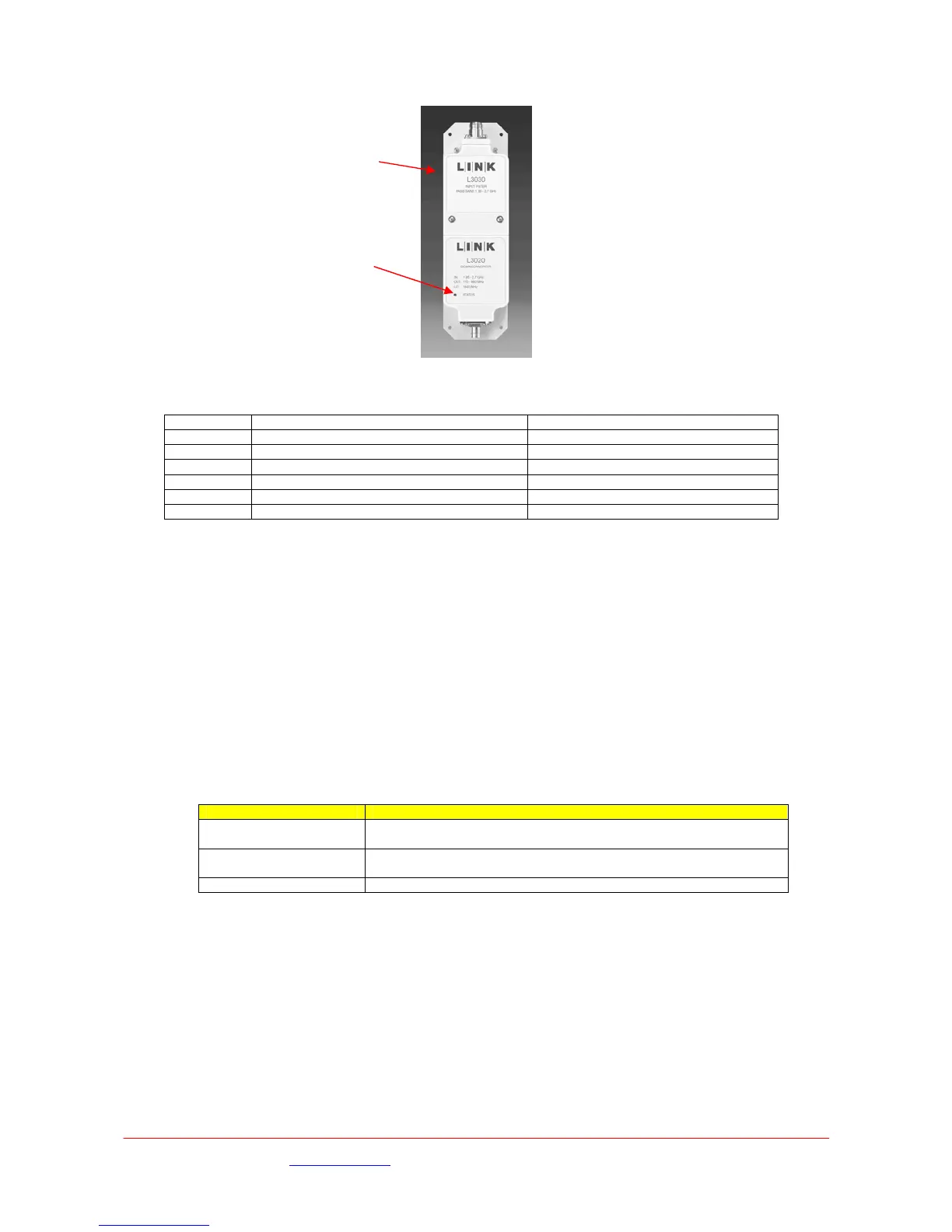
6.2 Mechanical
Changeable Filter
block
Downconverter
Base L3070/50
 Loading...