Other
Use this setting for other manufacturers down converters. The local
oscillator setting must be manually entered in the Demod menus.
By entering a value of 0 for the down converter local oscillator, the
receiver can be tuned in the range of 860MHz to 470MHz.
None With this setting, the receiver automatically tunes to 70MHz.
Unit PCB ###### None Not supported in this version of code.
Features None List of include features (engineering use only)
Battery None Feeds back status of Camera battery if CCU fitted
Tuner Version None Indicates version of the tuner board
Command None Generic command entry (engineering use only)
CCU Menu - Camera Control
Only available if connected to the L1255 data transmitter.
Sub menu Options Comments
Camera Type Select
camera type
Philips, Sony, Ikegami
(other options to be added)
Power Set power
output
Current L1255 CCU can be set between 0.1W to 2.0W
Frequency Enter
required
frequency
Set UHF transmitter frequency 450-470MHz
Status None Confirms communication status of L1255 CCU unit
Internal Uses internal modem and local RF power output Modem
(not Implemented
yet)
External Disables local RF output and allows CC serial data to be transmitted
down RS485 path to remotely situated L1255 Modem unit
Baudrate None Indicator of input baud rate. If set to 115200, it means that there is
no return data being sent back from the camera. When correctly
working should display 9600
Lock No Indicates lock. Power Reset if necessary
CCU Opt
5.3 Receiver Setup
The main functions that require configuration at the receiver are :-
• Type of down converter and operating frequency
• Demodulation scheme in operation; DVB-T, LMS-T or ASI input
• Frame Lock
• Audio Output
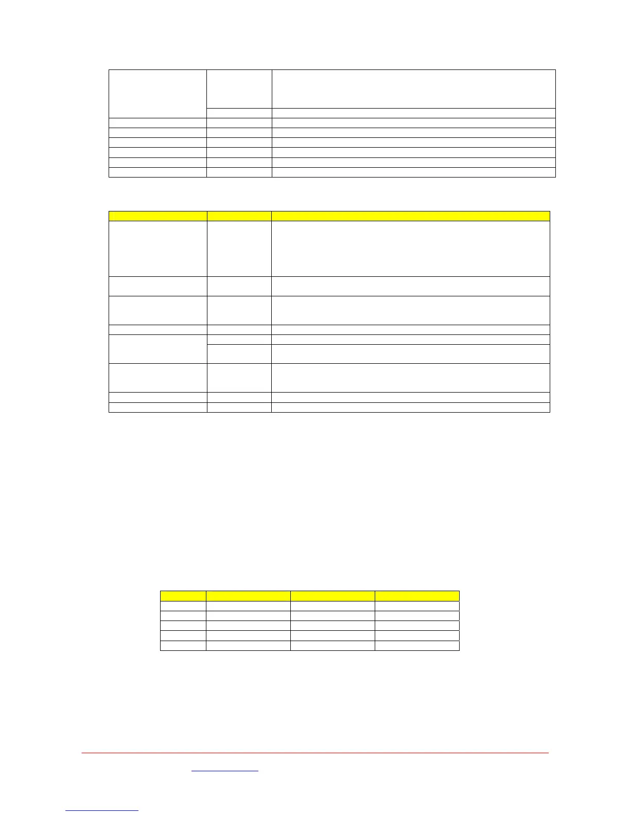
Down Converter Type
The following sequence defines the changes and sequence required when selecting the required down
converter and receiver RF frequency :-
Step Menu Option Setting
1 Unit DConv Type Select Type
2 Unit LNB Power On
3 Demodulator IPFreq As Required
4 Demodulator Guard Inv Match Transmitter
5 Demodulator Polarity Match Transmitter
The demodulator will then automatically detect code rate.
These received demodulation settings can be confirmed by checking the Demodulator menu.
Demodulation Options
Images are for illustration only and may differ from components supplied
Link Research Ltd www.linkres.co.uk Support UK/Europe + (44) 1923 474099 USA +(1)9786715700
Page 19 of 31 CL140045 Issue C Link L1500 Series System Manual
 Loading...