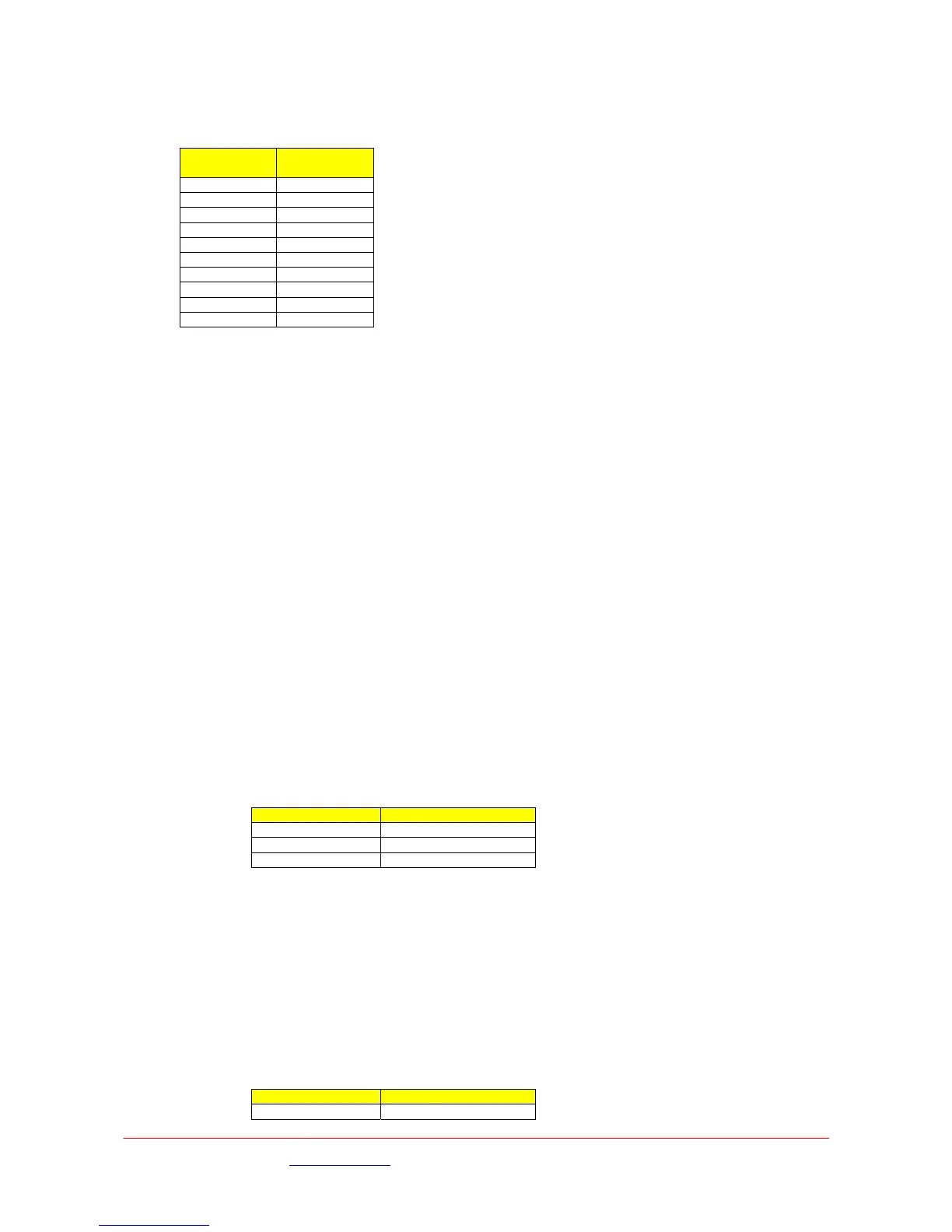
The L1500 will also accept SD inputs as either composite (CVBS), component (Y/Pr/Pb) or SDI in
the following formats :-
Standard
Input
Connector
SDI 625 SDI
SDI 525 SDI
PAL CV
NTSC CV
NTSC No Ped CV
PAL-M CV
PAL-N CV
YPbPr 625 Y/Pr/Pb
YPbPr 525 Y/Pr/Pb
Betacam Y/Pr/Pb
3.4 Input / Output Connections
This following section details the connector types and pin-outs of the interface connectors on the
L1500 Transmitter unit.
3.4.1 SDI Video Input
75Ω chassis mounted BNC jack socket for input of HD-SDI (SMPTE 292M) or SD-SDI (SMPTE 259M)
video.
3.4.2 SD Analogue Video Inputs
Three 75Ω chassis mounted insulated BNC jack sockets for input of composite (CV) or component
analogue (YPrPb) SD video. The CV and Y inputs share a common connector.
3.4.3 ASI
Both ASI input and ASI output are connected to the transmitter unit via 75Ω chassis mounted BNC
jack sockets.
3.4.4 Audio - Ch1
A stereo pair, differential inputs at Mic level (with or without phantom power) or Line Level. A
switched 25dB gain and a variable (+31.5 to -95dB) level control.
Line / Mic and phantom power is independently switchable on Ch1 and Ch2.
>20kΩ input impedance
Frequency response 50Hz to 15kHz <0.1dB
Frequency response 20Hz to 20kHz <0.5dB
+18dB clipping level (+18db ≡ 0dBFS)
2 Chassis Socket Connectors:- XLR3
XLR Pin Function
Pin 1 Gnd
Pin 2 Live / +ve
Pin 3 Ret / -ve
3.4.5 Audio - Ch2
A stereo pair, differential inputs at Mic level (with or without phantom power) or Line Level.
A switched 25dB gain and a variable (+31.5 to -95dB) level control.
Line / Mic and phantom power is independently switchable on Ch1 and Ch2.
>20kΩ input impedance
Frequency response 50Hz to 15kHz <0.1dB
Frequency response 20Hz to 20kHz <0.5dB
+18dB clipping level (+18db ≡ 0dBFS)
Chassis Socket Connector :- LEMO EEG0B305CLV
Mating Cable Plug :- LEMO FGG0B305CLAD52Z
Link Cable Assembly – 2 x XLR3 :- L0001
LEMO Pin Function
Pin 1 Left Line + (Line)
Images are for illustration only and may differ from components supplied
Link Research Ltd www.linkres.co.uk Support UK/Europe + (44) 1923 474099 USA +(1)9786715700
Page 12 of 31 CL140045 Issue C Link L1500 Series System Manual
 Loading...