SD The unit’s video is frame locked to an external source and will be
slightly delayed. If Framelock is set to on and no synchronising input
is detected, an alarm, GEN, flashes on the display.
NB – the colour sub carrier is not locked to the synchronising source.
SD mode uses black and burst mode to lock the frame
Framelock ###
HD HD uses the more accurate tri-level sync signal to lock the frame
Offset ##### pix
None Allows delay or advance of the framelock in the range of 0 – 9999
pixels. 5000 is the centre of the range. 1 pixel = approx 74.63 nano
seconds.
RS232 Menu
Sub menu Options Comments
Off Inhibits any RS232 data being output.
Data ###
On Allows RS232 data to be output. See remote control protocol for
details of data types and encoding settings.
Baud rate #### None Automatically detects the baud rate of the data stream. If no data is
detected, (null) is displayed.
Parity None Automatically detects the baud rate of the data stream.
Unit Menu
Sub menu Options Comments
Address # None Allows the unit address to be set where multiple receivers are
controlled from the same source. Used by the Link Control protocol.
A value between 0001 and 9999 can be set.
Yes Power is supplied via the down leads to the down converter. On the
display LNB ON is shown in the bottom left corner.
LNB Power ###
No There is no low voltage power supplied to the down leads.
Soft version: ### None Displays the version of the currently installed firmware.
FPGA A version: ##
None Displays the version of the currently installed FPGA code.
FPGA A version: ## None
HW Version None Currentrly displays two variants HW4000 or HW6000
SerNum ###### None Displays the electronic serial number of the unit.
Lcod ‘//////////
None Allows a unique hexadecimal string (licence code) to be entered so
that the unit’s features can be upgraded or downgraded. The hex
string is issued by Link providing the correct conditions (payment)
are satisfied.
Off Allows full control of all settings on the receiver. Lock ###
On Allows the User to scroll through the menus but will not allow any
changes to be made to settings – other than Lock Off ! A padlock
symbol is shown on the display when Lock is on.
LCD Contrast # None Allows the contrast of the display to be varied in 16 steps (0 to 16)
Mode #### 10MHzCOFDM 10MHz (Single) LMS-T modulation
20MHzCOFDM 2 x 10MHz (Dual) LMS-T modulation
None Demodulator disabled
DVBT DVB_T Standard
ASI Lock None Displays whether the decoder is locked to an incoming ASI stream
L3010 Use this setting for an older Link manufactured down converter. This
setting automatically enters the correct local oscillator frequency in
the Demod menus
L3014 Link down converter with 1.435GHz to 1.525GHz filter
L3030 Link down converter with 1.95GHz to 2.7GHz filter
L3031 Link down converter with 2.00GHz to 2.11GHz filter
L3032 Link down converter with 2.1GHz to 2.2GHz filter
L3033 Link down converter with 2.2GHz to 2.3GHz filter
L3034 Link down converter with 2.3GHz to 2.4GHz filter
L3035 Link down converter with 2.4GHz to 2.5GHz filter
L3037 Link down converter with 2.5GHz to 2.7GHz filter
L3060 Link down converter with 3.4GHz to 3.58GHz filter
L3080 Link down converter with 6.425GHz to 7.125GHz filter
L3085 Link down converter with 6.80Ghz to 7.5GHz filter
Dconv Type #####
More Downconverter options on request.
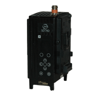
Images are for illustration only and may differ from components supplied
Link Research Ltd www.linkres.co.uk Support UK/Europe + (44) 1923 474099 USA +(1)9786715700
Page 18 of 31 CL140045 Issue C Link L1500 Series System Manual

 Loading...