SDI Video out
SDI #1 and SDI#2. Two independent SDI outputs for HD and SD output.
75Ω BNC chassis mounted socket for HD-SDI (SMPTE 292M) video output.
ASI out
ASI output from the demodulator for decoding by external Decoder.
75Ω BNC chassis mounted socket.
ASI Input
ASI input to the MPEG2 HD/SD decoder.
75Ω BNC chassis mounted socket.
Data/Remote/Alarm (L2132 Style units)
A ‘D’ Type sub connector that is used for RS232 data output, firmware download and alarm outputs.
9way ‘D’ Type Chassis mounted socket
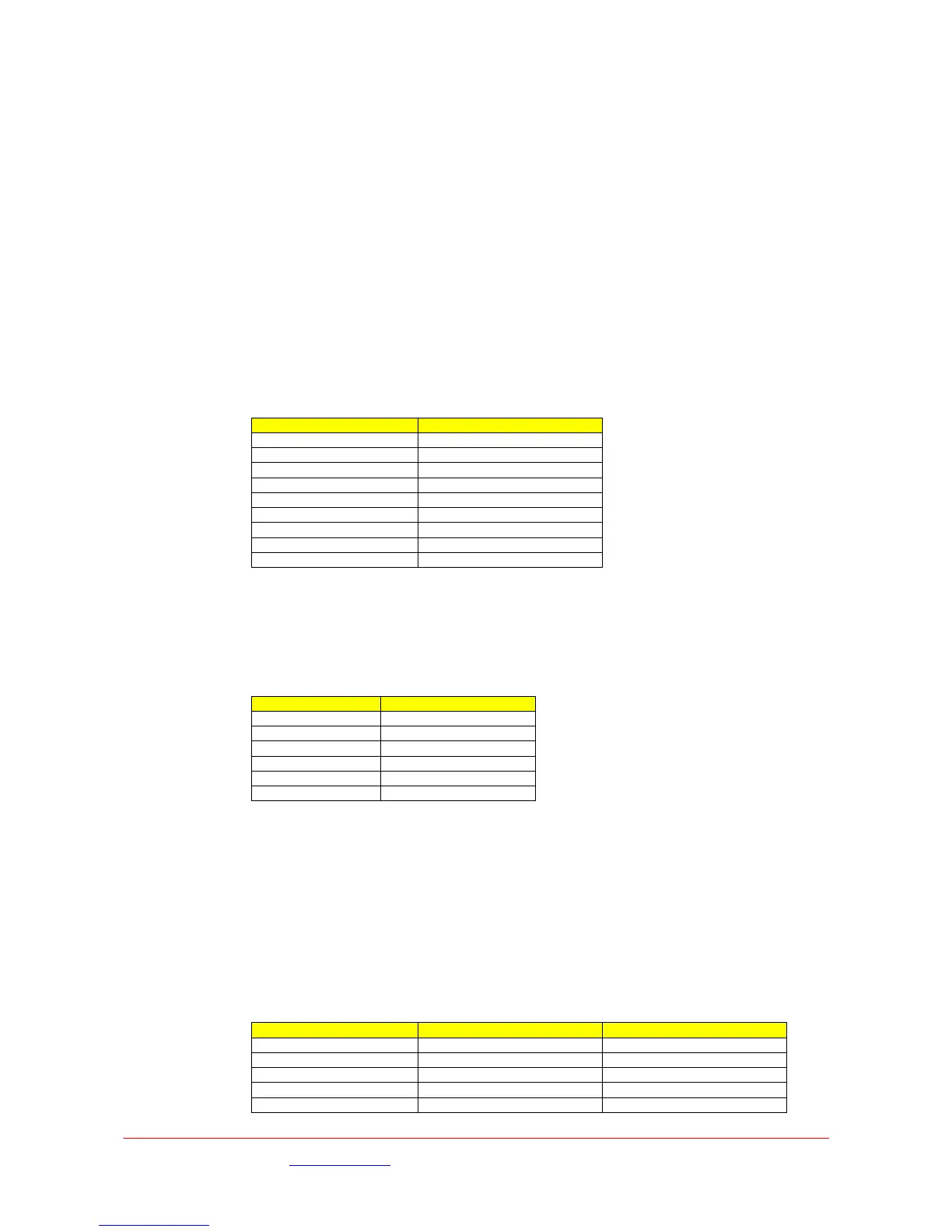
‘D’ Type Conn Function
Pin 1 Relay normally closed
Pin 2 Remote TX
Pin 3 Remote RX
Pin 4 Data in (diagnostic mode)
Pin 5 Data /Remote Gnd
Pin 6 Relay normally open
Pin 7 Remote TX enable
Pin 8 Data out
Pin 9 Relay common
Data/Remote (L2134 Style units)
The six pin connector provides the RS232 input / output of both the User Data and also Remote
Control of the transmitter unit.
Chassis Socket Connector :- LEMO EEF0B306CLV
Mating Cable Plug :- LEMO FGG0B306CLAD52Z
LEMO Pin Function
Pin 1 Tx Data (output)
Pin 2 Rx Data (input)
Pin 3 0v
Pin 4 Tx Control (output)
Pin 5 Rx Control (input)
Pin 6 0v
Audio
Two stereo pairs or 4 mono channels. A1 and A2. Two 5way XLR5 Male Chassis mounted plugs
These connectors are switched to provide either analogue or AES-EBU (digital) audio outputs. These
are switched independently via the Decoder/A or B Audio o/p/ menu
48kHz sampling
Clip level 18dB
THD < 0.1%
20Hz to 18kHz ±0.25dB
Crosstalk >60dB minimum
Signal to noise ratio >66dB RMS
XLR5 Conn Function - Analogue Function - AES
Pin 1 Audio Gnd Audio Gnd
Pin 2 Left + AES +
Pin 3 Left - AES -
Pin 4 Right +
Pin 5 Right -
Images are for illustration only and may differ from components supplied
Link Research Ltd www.linkres.co.uk Support UK/Europe + (44) 1923 474099 USA +(1)9786715700
Page 22 of 31 CL140045 Issue C Link L1500 Series System Manual
 Loading...