Images are for illustration only and may differ from components supplied
Link Research Ltd www.linkres.co.uk Support UK/Europe + (44) 1923 474099 USA +(1)9786715700
Page 27 of 31 CL140045 Issue C Link L1500 Series System Manual
Pin 4 DSR
Pin 5 0V
Pin 6 DTR
Pin 7 CTS
Pin 8 RTS
Pin 9 Power
Antenna
50Ω BNC connector for connection to the UHF antenna.
e function of the pins is
utomatically configured depending on the selected camera type.
ating Cable Plug :- LEMO FGG0B305CLAD52Z
Camera Control Data
Serial data interface to the camera head using appropriate lead. Th
a
Chassis Socket Connector :- LEMO EEG0B305CLV
M
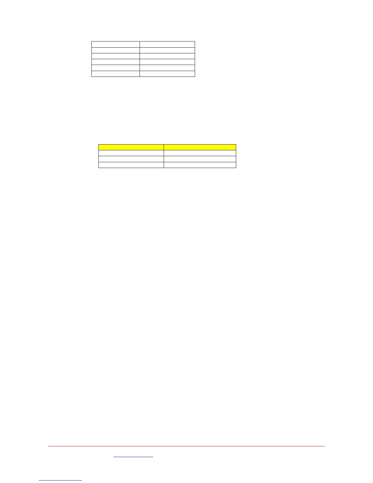
Lead ber Part Num Camera Type
L0016 Philips LDK Series
L0017 Son s y BVP Serie
L0024 Ikegami
.3.2 Mechanical
m - including rear panel connectors
mall form 1U, ½ width 19” rack mount
1.7kg weight
mbient 0ºC to +40ºC
AC input option 100VAC to 240VAC 50Hz to 60Hz
7
Height 44mm, Width 210mm, Depth 320m
S
~
A
7.3.3 Power
 Loading...