10
Level-Up®
Aftermarket Manual
www.lippertcomponents.com (574) 537-8900 Rev: 09.15 - Level-Up® Aftermarket Manual
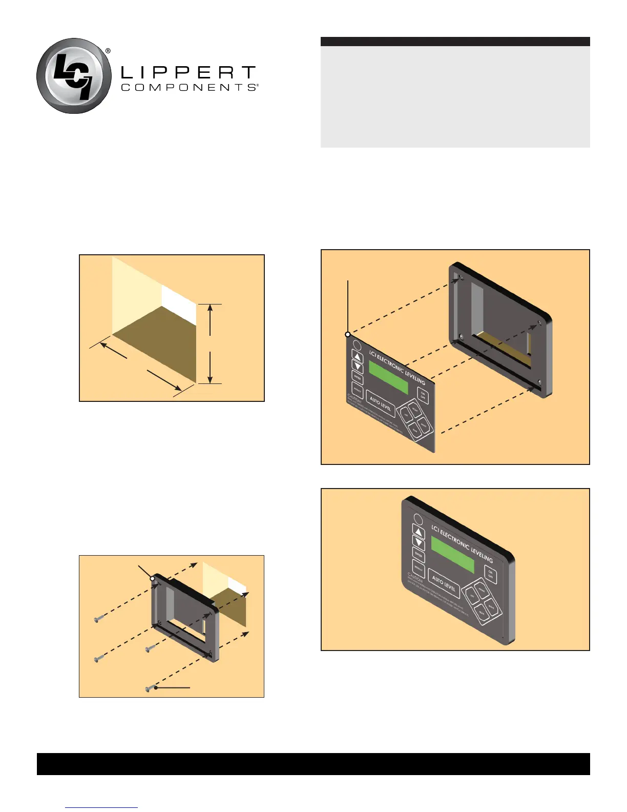
6. Plug the touch pad harness into the connector on the back
of the touch pad face plate and snap the face plate into the
bezel (Figs. 24 and 25).
Touch Pad
Face Plate
7. The last harness to connect is the one that powers and controls
The system. One end will have two connectors that plug into
the controller, a 9-pin and a 6-pin, and the other will have eight
color coded wires.
8. Connect the 9-pin and 6-pin connectors to the proper ports on
the controller.
2
3
/4 ”
3
3
/8 ”
Compartment Wall
Fig.22
Touch Pad
Bezel
Wood Screw
Fig.23
Fig.24
Fig.25
4. Feed the touch pad harness through this hole and
run it to the compartment where the controller is mounted.
Plug the harness into the appropriate connector on the
controller.
5. Insert the touch pad bezel into the cutout and attach it with
four #8x1” wood screws with sufficient length to thread into
the compartment wall (Fig. 23).
3. Cut a hole in the wall of the compartment 3
3
/8” wide by
2
3
/4” high so the top and bottom horizontal cuts are
parallel to the floor of the compartment (Fig. 22).