7
Level-Up®
Aftermarket Manual
www.lippertcomponents.com (574) 537-8900 Rev: 09.15 - Level-Up® Aftermarket Manual
Front Landing Gear
NOTE: Be sure to not cross thread the bolts and nuts.
5.InstalltheJIChydraulicttingsintothelandinggears.(See
Plumbing Diagram for orientation).
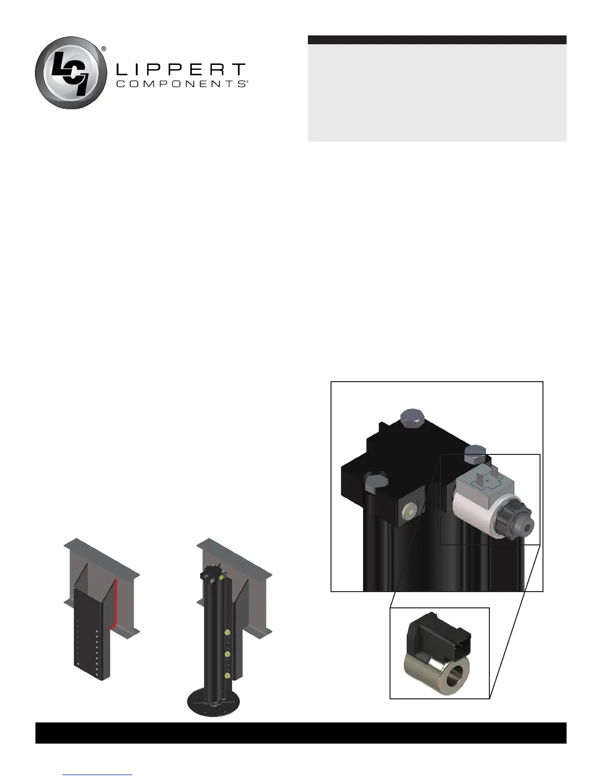
6. Install the cartridge valve and spade coil assembly into the lead
landing gear (Fig. 17).
NOTE: A sparkproof valve coil (Fig. 17 Detail) may be required if
the landing gear is installed in an LP compartment.
4. Connect the rear sensor harness to the connector on the
rear sensor and run the harness through the frame and up
to the compartment where the controller will be mounted.
1.Removeoldlandinggear.Ifnecessary,cutholesintheoor
pan of the front compartment to create more clearance to
install the new landing gear. Cover plates are included in the
parts kit to cover the holes.
2. Weld mounting bracket to I-beam (Fig. 15).
NOTE: When installing this system on a smaller frame, tack
welding the nuts on the backside of the mounting bracket prior
to welding the bracket to the frame will simplify tightening the
bolts when mounting the jacks.
3. Paint the mounting brackets and welded frame areas black
after the welds have cooled.
4. Slide the jacks into position on the mounting brackets. On
a straight frame, the jack should be positioned as low as
possible while maintaining at least 12” of ground clearance
when in the retracted position. On a drop frame, the jack
should be placed as high as possible in order to maintain at
least 12” of ground clearance. Use six bolts and nuts to attach
the jack to the mounting bracket (Fig. 16).
Fig.15 Fig.16
Fig.17
Fig. 17 Detail