8
Level-Up®
Aftermarket Manual
www.lippertcomponents.com (574) 537-8900 Rev: 09.15 - Level-Up® Aftermarket Manual
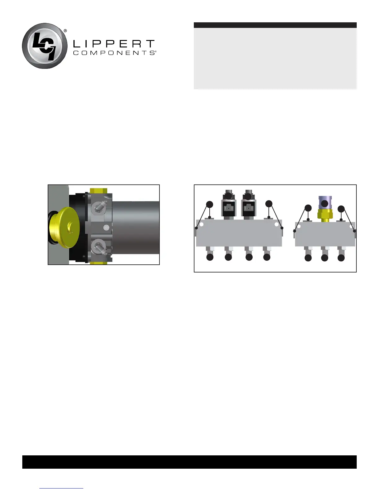
Fittings installed in power unit
Assembling and Mounting the Valve Blocks
1. Install two valve and coil assemblies in the Extend Valve block
(Fig. 19A & 19B) in the two center ports.
2.Install4straightJIC(Fig.19F,G,H,I)adaptersintothe4
ports across from the two valves you previously installed.
Install plugs (Fig. 19D) (removed from leveling jacks) into the
remaining ports.
3. Install the Pressure Switch (Fig. 19C) in the center port of the
retractvalveblock.Install3straightJICttings(Fig.19J,K,L)
into the 3 ports across from the pressure switch you previously
installed. Install plugs (Fig. 19E) (removed from leveling jacks)
into the remaining ports.
4. Cut a piece of 3/4” thick plywood into a rectangle large enough
to mount both valve blocks.
5. Mount the valve blocks to the plywood using 3” screws. Only
drive the screws far enough into the plywood to hold the valve
blocks in place. Do not pierce the back side of the plywood.
Mount the plywood to the back or side wall of the front
compartment next to the pump assembly using the screws
already holding the valve blocks in place.
NOTE: Do not overtighten mounting screws. Overtightening
may deform or damage the valve blocks causing them to
malfunction or leak.
Hydraulic Hoses
1.Connecttherearextendhoses(orange)totheJICttinginthe
extend valve block directly opposite of the two valves, (Figs.
19G&19H).Orientationisnotcriticalatthispoint,thevalve
coil wires can be switched to correct the function.
2.Connecttherearretracthose(black)totheJICttinginthe
retract valve block directly across from the pressure switch,
(Fig.19K).
3. Make hoses to connect the power unit to the valve blocks. 3’
lengthsshouldbesufcient;one(1)extend(orange)hose,and
one (1) retract (black) hose.
4. Connect the extend hose to the extend (DN) side of the power
unit,andthentotheJICttingontheextendvalveblock
closest to the power unit, (Fig. 19F).
5. Connect the retract hose to the retract (UP) side of the power
unit,andthentotheJICttingontheretractvalveblock
closest to the power unit, (Fig. 19J).
D
D
B
A
F G H I
E
E
C
J K L
Extend Valve Block
Retract Valve
Block
Power Unit
1. The power unit mounting location was determined when the
coachwasrstinspected.Mountthepowerunittotheback
or side wall of the front compartment in the position you
previously determined using six (6) self tapping screws.
2.Installhosettingsintothepowerunit(Fig.18).Thetwoports
are marked DN and UP. DN = Extend. UP = Retract.
Fig.18 Fig.19