3
Level-Up®
Aftermarket Manual
www.lippertcomponents.com (574) 537-8900 Rev: 09.15 - Level-Up® Aftermarket Manual
1. Use the checklist on the previous page to provide a guideline for
setting up the Level Up install.
2. Determine how and where the leveling jack brackets will be
welded to the frame of the coach.
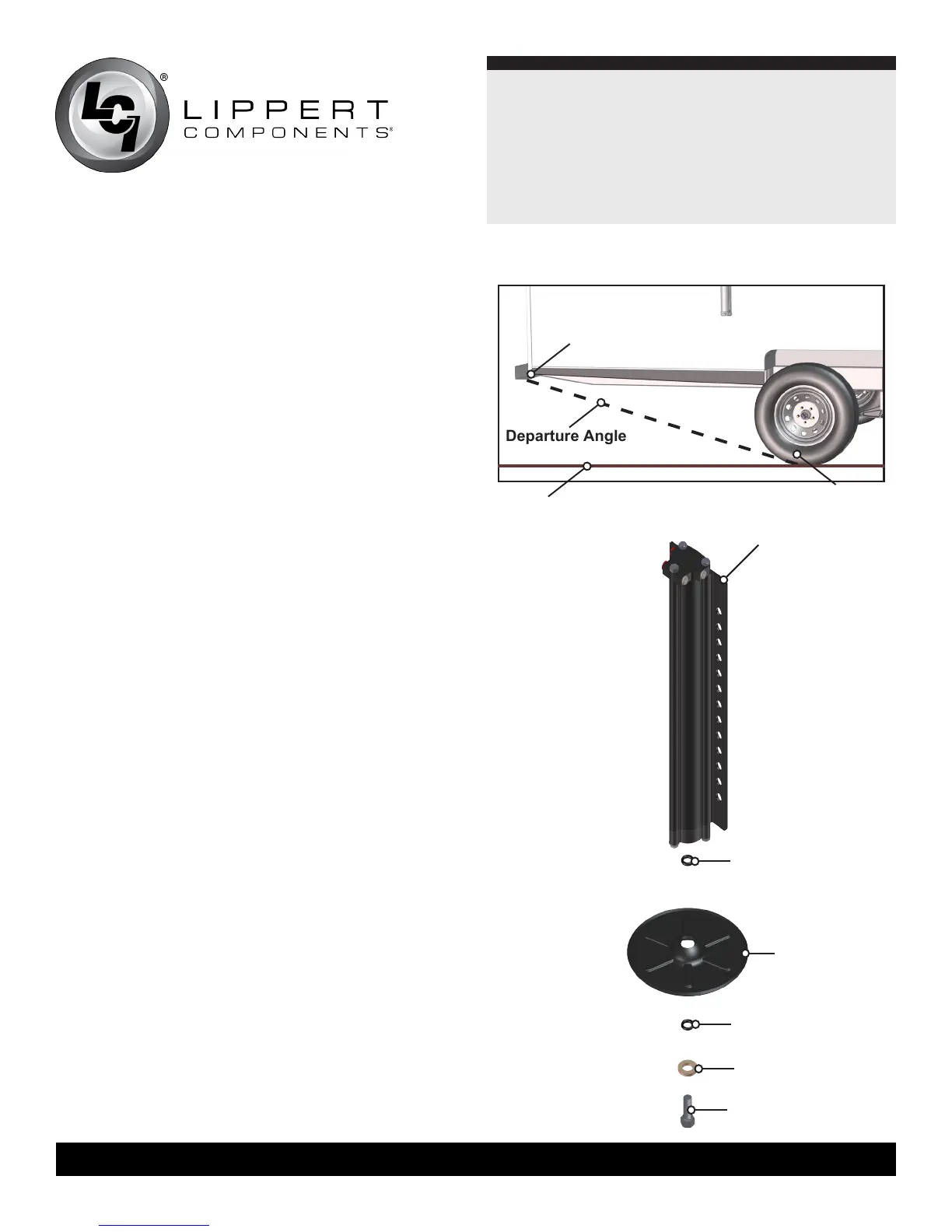
NOTE: The rear Level Up jacks should be mounted approximately
behind the rear tires, within the plane of the departure angle
(Fig. 1), and aligned with each other. The front Level Up
jacks should be mounted approximately 1 foot in front of the
front tires. Front jacks can be offset up to 24 inches to clear
obstructions, i.e. entry steps. Determine the location of the
current power unit (if one is already on the coach) or where the
new power unit and valve manifolds will be mounted.
3.Checkforanyobstructionsthatwillrequiremodicationofthe
brackets prior to welding (slide-out cross shafts, outriggers, or
manual override connections for slide-outs).
4. Extend all slide-out rooms. This will clear space for welding the
Level Up brackets by moving the fender skirts out of the way.
5. Drop the underbelly from the outside edge of the unit. Start on
the side closest to where the pump will be located and un-bolt
the underbelly from the front of the unit to approximately 2 feet
beyond the rear tire. On the opposite side of the unit, un-bolt
the underbelly from approximately 2 feet behind the rear tire
to approximately 2 feet in front of the front tire. Do not remove
any bolts from the center of the underbelly. Do not drop the
entire underbelly. Attaching and aligning the entire underbelly
will be more difficult than working around the underbelly.
6. Locate and move any wires, hoses, etc. that could be damaged
while welding the jack brackets to the frame. Check both
inside and outside of the frame. Shields made of metal or
wood can be used to push wires and hoses away from the
frame area where welding is to be done.
7. Bolt the footpads to the jacks and torque to 132 ft/lbs. Make
sure to use Loctite® on the footpad bolts. See bolt in (Fig. 2)
assembly for reference.
NOTE: Do not try to remove the bolt once it is tightened.
Removing the bolt could result in damage to the cylinder.
Leveling Jack
Departure Angle
Ground
Rear Tire
O-Ring
Foot Pad
O-Ring
Washer
Bolt
Fig.1
Fig.2
Lowest Point on
Rear of Coach