5
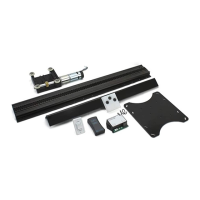
Level-Up®
Aftermarket Manual
www.lippertcomponents.com (574) 537-8900 Rev: 09.15 - Level-Up® Aftermarket Manual
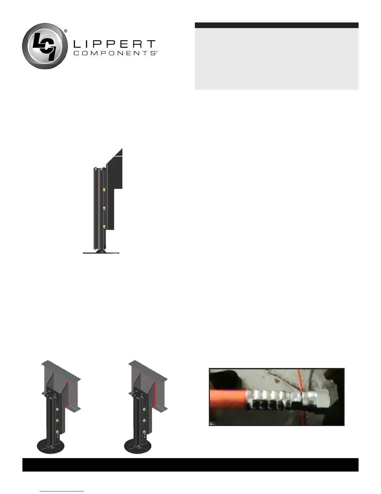
7.Marktheneededmodicationsonthejackbrackets(Fig.8).
8. Using a cutting torch or plasma cutter, cut the material from
the bracket, being careful not to damage the leveling jack or
ttingsattachedtoit.
9. Fit the mounting bracket against the I-Beam, making sure
thatthebottomedgeofthemountingangeisushwiththe
bottom lip of the I-Beam.
10. Tack weld the top and bottom corners of each side of the
mountingange(Fig.9).
11. By implementing a 1/4” weld bead, fully weld the bracket to the
I-Beam from top to bottom on both sides of the bracket (Fig.
10). Make sure to avoid any hoses or wiring that may be in the
welding area.
12. Repeat this welding process for the remaining 3 leveling jacks.
13. Paint the mounting brackets and welded frame areas black.
14. Measure and make the hydraulic hoses (orange for extend,
black for retract). Measure from the rear leveling jack to the
front leveling jack. Add 3 feet to this measurement to ensure
that there will be enough hose material to mount between
jacks and prevent kinking. This will be the measurement for
the extend and retract hoses between the two jacks on either
side. For example, if the measurement is 9 ft., two 12 ft.
orange hoses and two 12 ft. black hoses would be made. One
9 ft. black hose will need to be made to connect the two rear
jacks on the retract plumbing.
15. Measure from the power unit location to the front leveling jack
on the side of the coach closest to the power unit location.
Add 3 feet to this measurement. This will be the length of
the retract and extend hoses from the power unit to the front
leveling jack on the side of the coach closest to the power unit.
Add 6 feet to that length and make one extend hose to run
from the power unit to the front leveling jack on the opposite
side of the coach. All hoses must be run on top of the foil
insulation inside the underbelly and over the top of any frame
crossmembers. See the plumbing diagram for full details on
the measuring, making, and installation of these hoses.
NOTE: When running the hoses from the power unit to the rear
leveling jacks, bundle them together with the harness for the
rear sensor and run them all at once.
Proper hose crimping example
Fig.8
Fig.9 Fig.10
Fig.11