Rev: 03.25.19 Page 40
CCD-0001447
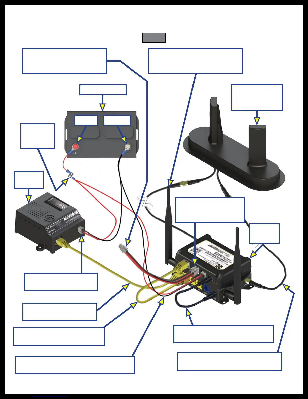
Fig. 67
Router LAN-to-Cellular Gateway
LAN Ethernet Patch Cable
Two 2.4GHz Wi-Fi Antennae
Connect to 2.4GHz Ports Located
on Both Sides of the Router.
Power
4G Externally
Mounted
Cellular Antenna
12V DC Battery
Ground
Circuit
Protection
Terminal
Cloud
Gateway
Cloud Gateway-to-Router
LAN Ethernet Cable
Router-to-Cellular Gateway
2.1mm 12V DC Plug Power Harness
Two CAN bus Harnesses
or One Harness and a
Terminating Resistor
12V DC Power Connector
Connects to Battery
Cellular
Gateway
Existing 12V DC Power Connector
Connects from System to Cellular Gateway
Existing CAN bus Harnesses
from a System Controllers
Connects to Cellular Gateway
System Wiring Diagram
Figure 67 shows key system interconnections of the ConnectAnywhere system.
Two 4G Cellular Coaxial Cables
Connect to External Antenna Pigtails