12
lci1.com 574-537-8900 Rev: 03.21.19
Solera
®
Universal Hardware
Manual Awning to
Solera 18V Power Awning
(For Aftermarket Applications)
CCD-0001267
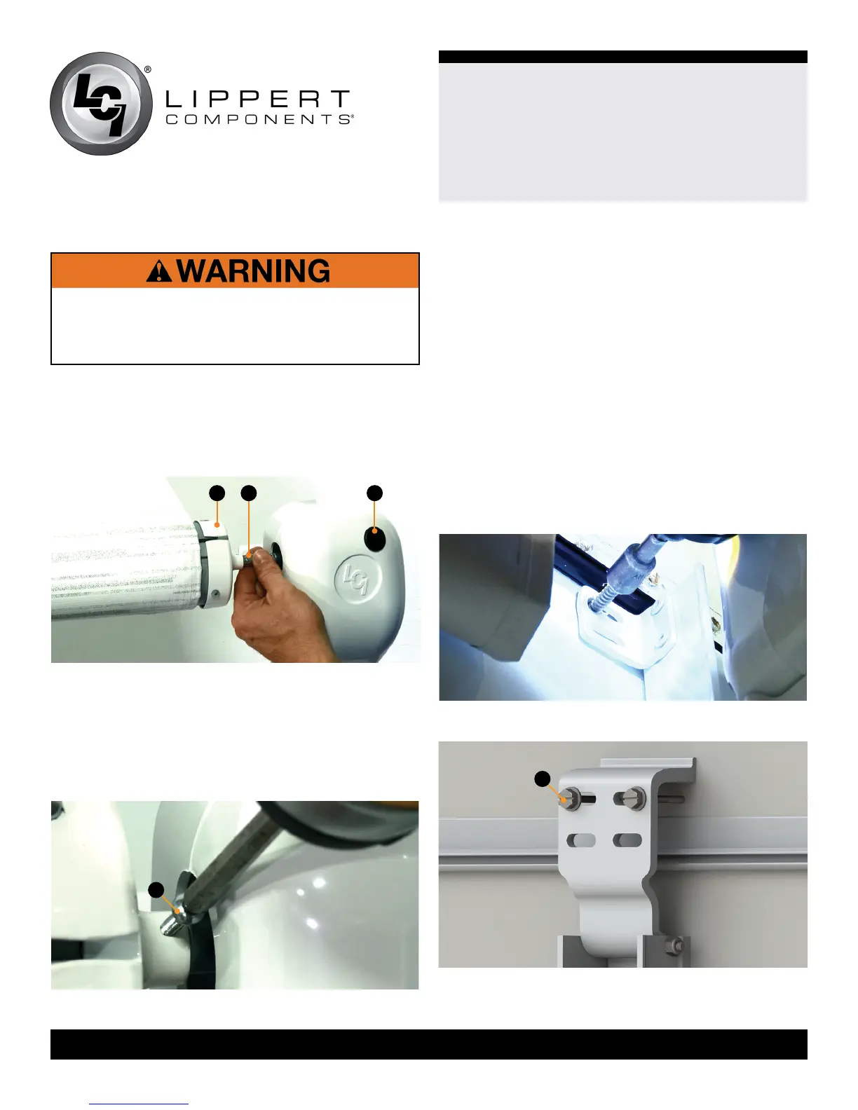
A C B
Fig.26
Fig.27
FAILURE MAINTAIN CONTROL OF THE ROLL TUBE
AND HEAD MAY RESULT IN DEATH, SERIOUS
INJURY, DAMAGE TO THE UNIT AND/OR VOIDING A
WARRANTY.
15. Insert the Solera drive head assembly shaft (Fig.26B)
into the end cap (Fig.26A).
NOTE: When determining the drive head assembly from
the idler head assembly, the drive head assembly will have
an override plug (Fig.26C), while the idler head assembly
will not.
16. Align the holes from the shaft on the head to the end
cap and secure with the provided #8 - 32 x ½” wax screw
(Fig.27A).
NOTE: Keep the head of the wax screw ⁄” from fastened
to avoid compromising the structural integrity of the wax
screw.
A
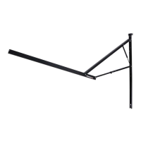
17. To secure the drive support arm assembly:
A. If using the original angle bracket on the new support
arm assembly, place the drive support arm assembly
directly under the awning rail so the top of the mount
arm is touching the bottom of the rail. Secure the upper
section of the drive mount arm to the unit with the
provided #14 x 1 ¼” screws, aligned directly below the
holes of the awning removed (Fig.28).
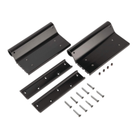
B. If using the upper mounting bracket, attach the upper
mounting bracket (Fig.29A) of the assembled support
arm assembly, using the previously removed screws.
Go through the top holes of the upper mounting bracket
and into the pre-existing holes in the wall of the unit.
All screws supporting the awning assembly MUST have
a backer within the structure of the wall of the unit.
Fig.28
Fig.29
A