Rev: 09.19.23 Page 17 CCD-0007153
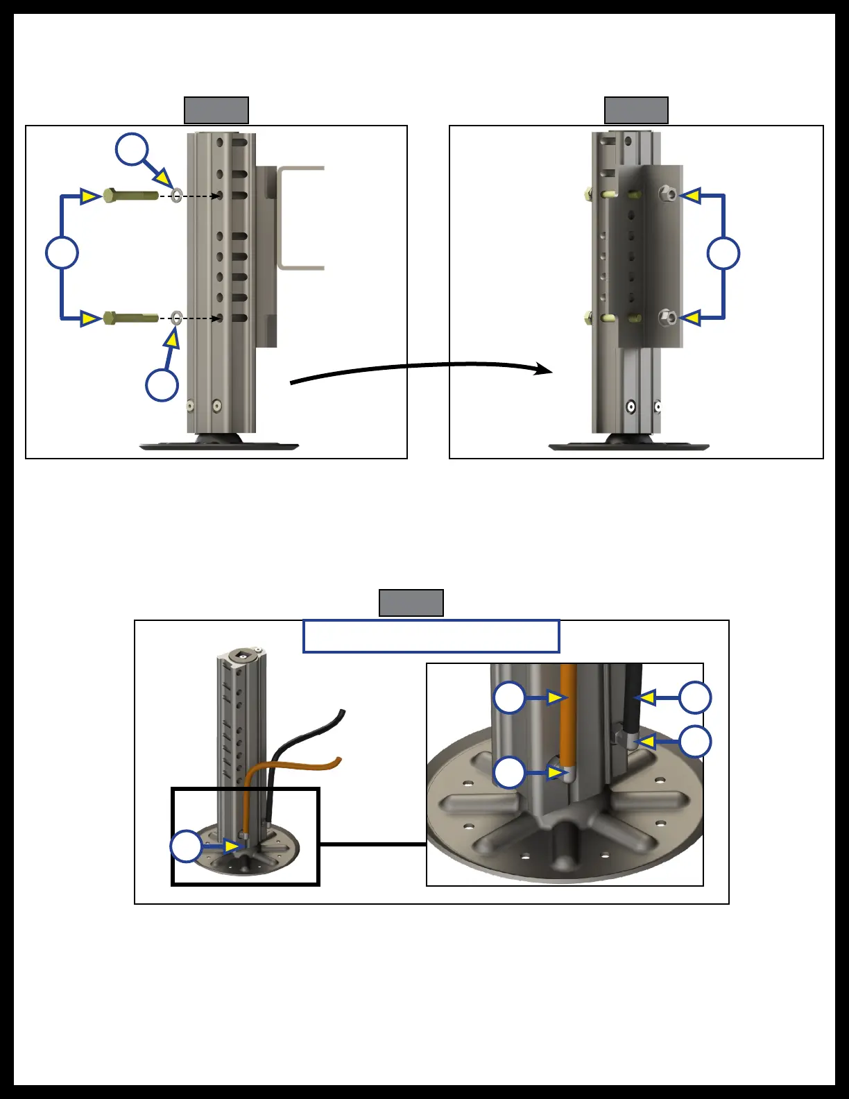
Fig. 37 Fig. 38
1/2” - 13 lock nuts (Fig. 38A). Torque to 90 ft/lbs.
NOTE: Frame rail is not shown in Fig. 38 to allow nuts to be seen in the image.
A
B
B
A
6. At the bottom of the inside face of the jack (Fig. 39A), remove the retract and extend port plugs and
attach two JIC 90 degree elbow retract fittings (Fig. 39D). Attach the pre-measured orange retract
(Fig. 39B) and black extend hoses (Fig. 39C).
7. Repeat steps 1-6 for the opposite side.
8. Attach the opposite ends of the extend and retract hoses to the hydraulic pump. See the Hydraulic
Plumbing Diagram section in this manual.
D
D
C
Driver's Side Rear Jack Assembly
B
A
Fig. 39