Rev: 09.19.23 Page 18 CCD-0007153
LED Touchpad / Controller Installation
NOTE: Images used in this document are for reference only when assembling, installing and/or operating
this product. Actual appearance of provided and/or purchased parts and assemblies may differ.
Images used in this document are for reference only when assembling, installing and/or operating
this product. Actual appearance of provided and/or purchased parts and assemblies may differ.
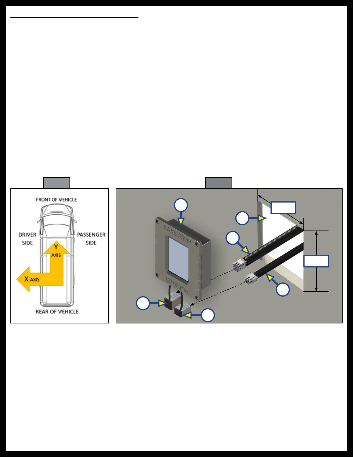
The front panel orientation of the touchpad / controller must be either in an X axis orientation or Y axis
orientation (Fig. 40). The front panel screen is splash resistant but is not water proof and should be installed
inside of the coach.
1. In the designated mounting location, cut a hole (Fig. 41B), 4 1/4" square, for the bezel of the
LED touchpad / controller (Fig. 41A) to fit into.
2. Attach and the LED touchpad/controller 9 pin harness (Fig. 41C) to the 9 pin power unit harness
(Fig. 41D) and feed through the pre-cut hole (Fig. 41A), running the opposite end of the wire harness
to the hydraulic power unit. See the Wiring Diagram in this manual.
3. Attach and the LED touchpad/controller 6 pin harness (Fig. 41E) to the 6 pin chassis harness
(Fig. 41F) and feed through the pre-cut hole (Fig. 41B), running the opposite end of the chassis
wire harness to the ignition positive power source and the parking brake ground. See the Wiring
Diagram in this manual.
Fig. 40 Fig. 41
C
E
B
D
F
A
4 1/4"
4 1/4"