Rev: 09.19.23 Page 6 CCD-0007153
Fig. 3
Installation
Prior to Installation
Refer to the Hydraulic Plumbing Diagram in this manual for the following steps:
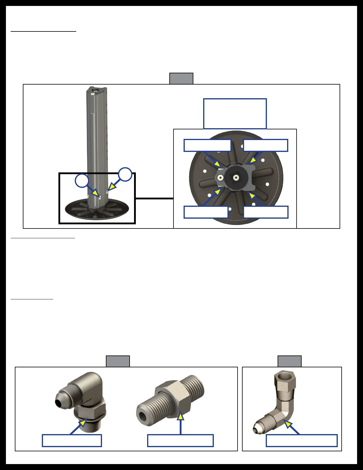
1. Identify where the extend (Fig. 3A) and retract ports (Fig. 3B) are on the jack.
2. Verify that the ports are clear of any residual machining metal debris.
3. Label each jack Left Front (LF), Right Front (RF), Right Rear (RR) or Left Rear (LR).
Jack Specifications
Because of various possible configurations, this manual will provide instructions with the hydraulic power unit
mounted near the center of the coach frame, roadside frame rail. Fittings and hose configurations may be OEM
specific. Under normal installation procedures, the jacks closest to the hydraulic power unit get plumbed first.
See the Hydraulic Plumbing Diagram in this manual for the hydraulic power unit located on the left side of
the coach.
CAPACITY - 8,000 lbs. max. STROKE - 13" FOOTPAD 9" DIA. STANDARD
Extend Port
Extend Port Retract Port
Retract Port
A
B
Top view of the
jack, without
hydraulic fittings.
Jack Fittings
1. The hydraulic fittings (Fig. 4) for the hydraulic power unit (Fig. 6) can be installed per figure 6 and the
Hydraulic Plumbing Diagram in this manual. Remove the port plugs corresponding to the appropriate
hoses needed for each jack at their respective location, see Hydraulic Plumbing Diagram (Fig. 50).
Use JIC swivel 90° elbow fittings (Fig. 5) for the jacks and jack hose connections. All jack fittings should
be on the inside face of the jack, towards the center of the coach.
Fig. 4
JIC Elbow Fitting JIC Swivel 90° ElbowJIC Straight Fitting
Fig. 5