Rev: 09.19.23 Page 9 CCD-0007153
Hydraulic Hoses
NOTE: Verify that the hydraulic fittings were installed on the four jacks and hydraulic power unit correctly.
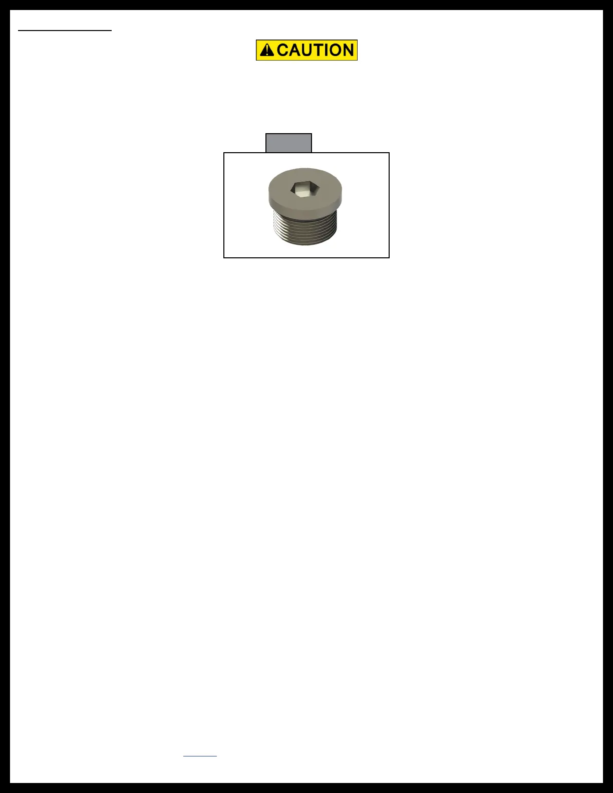
A 7/16” port plug (Fig. 12) will be used to seal any ports not used within the system.
When installing hydraulic hoses, avoid areas of high heat, e.g. exhaust outlets. Do not use sharp or abrasive
materials on or near hydraulic hoses.
• Left Front Extend
• Right Front Extend
• Left Rear Extend
• Right Rear Extend
1. Measure the distance between the left front jack and the hydraulic power unit; this is an extend hose
(Fig. 66A).
2. Measure the distance between the right front jack and the hydraulic power unit; this is an extend hose
(Fig. 66B).
3. Measure the distance between the left rear jack and the hydraulic power unit; this is an extend hose
(Fig. 66C).
4. Measure the distance between right rear jack and the hydraulic power unit; this is an extend hose
(Fig. 66D).
5. Measure from the left front jack to the front manifold extend fitting on the hydraulic power unit; this is
a retract hose (Fig. 66E).
6. Measure from the left rear jack to the rear manifold extend fitting on the hydraulic power unit; this is a
retract hose (Fig. 66F).
7. Measure from the right front jack to the front extend fitting on the hydraulic power unit; this is a retract
hose (Fig. 66G).
8. Measure from the right rear jack to the rear extend fitting on the hydraulic power unit; this is a retract
hose (Fig. 66H).
NOTE: Make sure hydraulic hose line fittings are compatible with the hydraulic power unit fittings and the
jack fittings. Make sure hose fittings are securely crimped onto the hose lines.
9. When running the hydraulic hoses from the hydraulic power unit to the jacks, bundle the hoses together.
Secure any loose hoses with zip ties as needed.
10. Install all hoses onto the corresponding jacks and hydraulic power unit fittings.
NOTE: Hose loops should be secured in the horizontal position to prevent trapped air pockets.
NOTE: Before operating the Lippert hydraulic leveling system, make sure the system has been properly
purged of air that was introduced into the hydraulic lines during the installation.
NOTE: If necessary, refer to TI-118 for Hydraulic Operation Fluid Recommendation.
• Left Front Retract
• Right Front Retract
• Left Rear Retract
• Right Rear Retract
NOTE: Refer to the Hydraulic Plumbing Diagram in this manual for fitting placements and for steps 1 - 8.
Labels on hoses:
Fig. 12