Rev: 09.19.23 Page 32 CCD-0007153
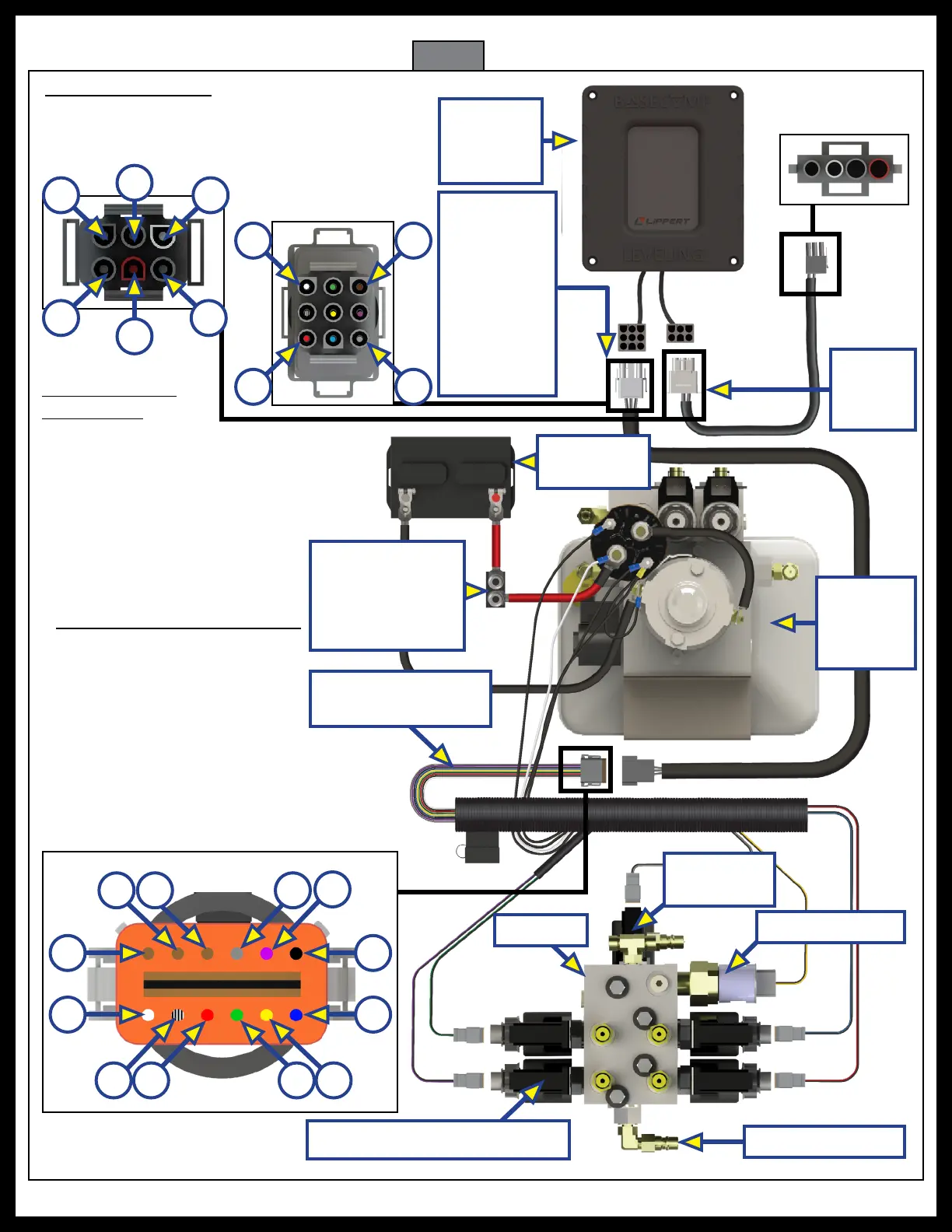
Wiring Diagram
12-Pin Power Unit Wire Harness
1. White (Chassis Power)
2. Black w/ White (Pump Solenoid)
3. Red (Curbside Rear Valve)
4. Green (Roadside Front Valve)
5. Yellow (PSI Switch)
6. Blue (Roadside Rear Jack Valve)
7. Black (Ground)
8. Purple (Curbside Front Jack Valve)
9. Gray (Directional Valve)
10. Aux
11. Aux
12. Aux
12
1
7
6
11
8
10 9
2 53 4
Manifold
Directional
Valve
Pressure Switch
Fig. 67
LED
Touchpad
Controller
Valves with Deutsch Coils
Battery
9 Pin Power
Unit Wire
Harness
to LED
Touchpad
Controller
12 Pin Hydraulic
Power Unit Harness
Quick Disconnect
4 Valve
Hydraulic
Pump
6 Pin
Chassis
Harness
6-Pin Chassis Harness
1. White (Parking Brake Ground)
2. Pink (LED Power)
3. Black (LED Ground)
1
2
4
5
6
3
4. AUX
5. Red (Ignition Source12V)
6. AUX
9-Pin Power Unit
Wire Harness
1. White (Control 12V Power)
2. Black w/ White (Pump Solenoid)
3. Red (Curbside Rear Valve)
4. Green (Roadside Front Valve)
5. Yellow (PSI Switch)
6. Blue (Roadside Rear Jack Valve)
7. Brown (Ground)
8. Purple (Curbside Front Jack Valve)
9. Gray (Directional Valve)
Circuit Protection
mandatory per
RVIA Standards
and OEM
Requirements
7
93
1