Rev: 09.19.23 Page 7 CCD-0007153
Hydraulic power unit Installation
NOTE: The location where the hydraulic power unit will be installed should be as near center on the coach as
possible. Install the hydraulic power unit in accordance with RVIA Gas Codes, since the hydraulic power
unit connections are not spark proof.
2. Identify the hydraulic power unit mounting location. This will determine the orientation of the hydraulic
fittings (Fig. 6). The recommended location for the hydraulic power unit is on the inside driver side frame
rail behind the fuel tank, with the motor pointing towards the rear of the coach.
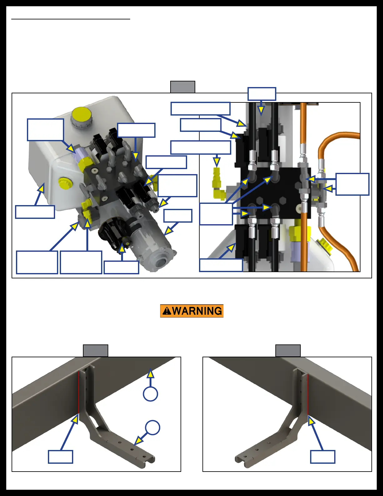
Motor
Fig. 6
Reservoir
Pressure
Switch
Motor
Valve Coil
Solenoid
Quick Disconnect
Retract
Fittings
Cartridge Valve
Valve Coil
Extend
Fittings
Manifold
Quick
Disconnect
Directional
Valve
Cartridge
Valve
Valve Coil
3. Protect any wires, hydraulic hoses, heat duct, gas lines, water/holding tanks and any other underbelly
material that is secured to, or resting against, the frame or I-beams that might cause a fire hazard.
4. Weld each side of the hydraulic power unit bracket (Fig. 7A) to the coach frame (Fig. 7B).
Fig. 7 Fig. 8
A
B
Weld
Weld
Failure to remove ammable objects or obstructions may result in death, serious
injury, or property damage.