Rev: 09.19.23 Page 10 CCD-0007153
Front Jack Bracket and Jack Installation
NOTE: The E450 chassis requires certain holes on the Titan Jacks to be utilized for successful installation
and system operation. Do not use other holes than the ones indicated when installing the jacks.
NOTE: 6-7.5" of ground clearance is recommended between the bottom of the front jack footpads and
the ground. If additional ground clearance is required, it may be added so long as the approach and
departure angles are not interrupted. See the "Preparation" section of this manual.
1. Protect any wires, hydraulic hoses, heat duct, gas lines, water/holding tanks and any other underbelly
material that is secured to, or resting against, the frame or I-beams that might cause a fire hazard.
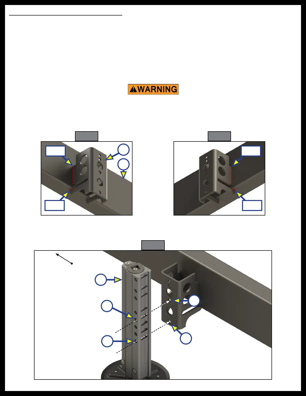
2. Weld the jack bracket (Fig. 13A) to the outside of the chassis beam (Fig. 13B). Weld on each side of the
Fig. 13
bracket where indicated by the red lines in Fig. 13 and Fig. 14.
3. Fit the Titan Jack (Fig. 15A) to the jack bracket by lining up its bottom mounting hole (Fig. 15B) to the
Fig. 14
Fig. 15
Failure to remove ammable objects or obstructions may result in death, serious
injury, or property damage.
bottom hole of the jack bracket (Fig. 15C). Also align the fourth mounting hole from the bottom on the
Titan Jack (Fig. 15D) and the middle mounting hole on the jack bracket (Fig. 15E).
4. Secure the jack by using two 1/2” - 13 X 3 1/2” bolts (Fig. 16A), two 1/2" split washers (Fig.16B) and two
Front of Coach
A
B
Weld
WeldWeld
Weld
C
E
D
B
A