Rev: 09.19.23 Page 19 CCD-0007153
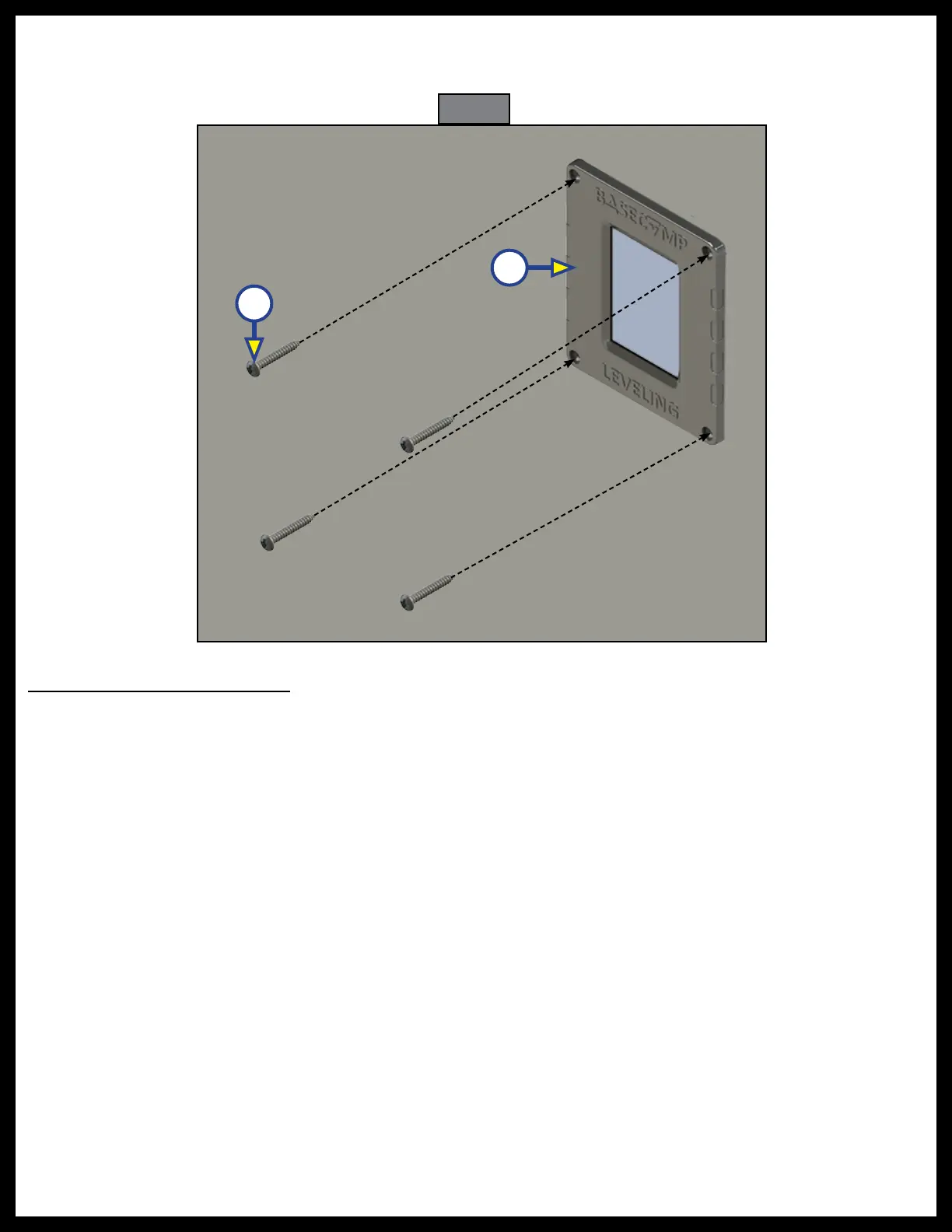
4. Insert the touchpad (Fig. 42A) into the cutout hole, and attach it to the mounting surface with four
#6 x 1" wood screws (Fig. 42B). Verify that the screws are of sufficient length to thread into the
mounting surface.
System Wiring Requirements
NOTE: Ground wires are OEM supplied.
1. Battery power cable with an OEM-supplied breaker (RVIA standard).
2. Battery ground cable (RVIA standard) connecting the 12V DC battery, to the ground post on the
hydraulic power unit motor.
NOTE: Lippert recommends connecting the ground cable directly to the battery, rather than a chassis
ground point.
3. Leveling jack status input - pressure switch.
A. Jacks not all up – switch closed to ground .
B. Jacks all up – switch open.
4. Connect the six-pin chassis harness to the "Ignition On" wire and the parking brake signal wire.
A. White - Parking Brake (open = park brake disengaged, GND = park brake engaged).
B. Red - 12v Ignition, Logic power (ignition switch controlled).
A
B
Fig. 42