Rev: 09.19.23 Page 12 CCD-0007153
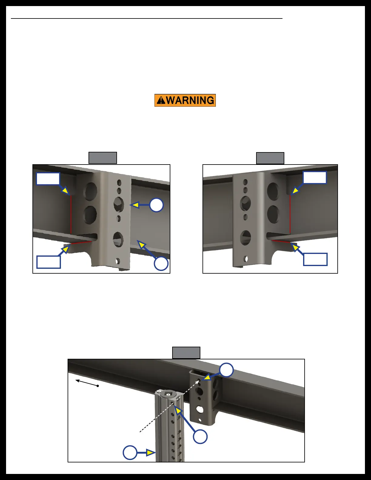
Fig. 19
Fig. 20
Rear Jack Bracket, Jack, and Crossbar Beam Installation (Inside Mount Option)
NOTE: The E450 chassis requires certain holes on the Titan Jacks to be utilized for successful installation
and system operation. Do not use other holes than the ones indicated when installing the jacks.
NOTE: If additional clearance is required, it may be added so long as the approach and departure angles
are not interrupted. See the "Preparation" section of this manual.
1. Protect any wires, hydraulic hoses, heat duct, gas lines, water/holding tanks and any other underbelly
material that is secured to, or resting against, the frame or I-beams that might cause a fire hazard.
2. Weld the jack bracket (Fig. 19A) to the inside of the chassis beam (Fig. 19B). Weld on each side of the
Fig. 21
bracket where indicated by the red lines in Fig. 19 and Fig. 20.
3. Measure the distance between the rear end of the chassis beam and the rear edge of the newly welded
A
B
Weld
Weld
Weld
Weld
Front of Coach
C
B
A
Failure to remove ammable objects or obstructions may result in death, serious
injury, or property damage.
jack bracket. Record this measurement.
4. Move to the chassis beam on the opposite side, and measure from the rear end of it equal to the
measurement you recorded earlier. Make a mark using an erasable, soft utensil.
5. Line up the rear edge of another jack bracket to this chassis beam at the previously made mark, and
weld it in place. Follow step 1 for welding locations and instructions.
6. Fit the Titan Jack (Fig. 21A) to the jack bracket by lining up its top mounting hole (Fig. 21B) to the top
mounting hole of the jack bracket (Fig. 21C).
7. Secure the jack by using a 1/2” - 13 X 3 1/2” bolt (Fig. 22A), 1/2" split washer (Fig.22B) and 1/2” - 13 lock